background image

5-4 FORK LIFT ATTACHMENT

WARNING

TO AVOID SERIOUS INJURY OR DEATH:

NEVER LIFT LARGE ROUND HAY        
BALES OR OTHER LOADS ON THE
FORK LIFT ATTACHMENT THAT 
COULD ROLL BACK ONTO TRAC-
TOR OPERATOR AREA.

NEVER USE FORK LIFT ATTACH-
MENT TO LIFT OR SUPPORT
PEOPLE.

TRANSPORT LOADS LOW AND 
SLOW.

AVOID CONTACT WITH POWER 
LINES.

The fork lift attachment (Figure 5-4) is intended for
handling palletized material. It is recommended that
tractor be equipped with ROPS and seat belts. Use

ASSEMBLY
1. Remove all cotter pins.
2. Slide fork pin out enough to place fork tine 

between bracket.

3. Slide fork pin through the fork tine and back 

through bracket and bushing.

4. Aligh cotter pin holes on fork lift frame and fork 

pin and replace bushing.

5. Spread cotter pin so it cannot work free.
6. The loader lifting capacity is approximately 75%

of the rated capacity at 24” from the face of the 
fork tine.

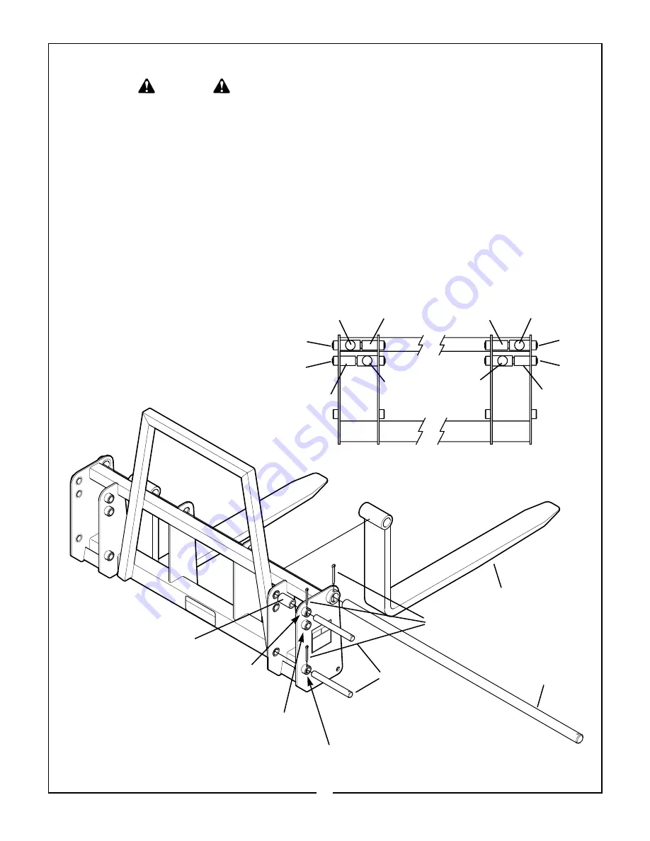
Figure 5-4 Fork Lift Attachment

Hydraulic

Cylinder

Hydraulic

Cylinder

Hitch

Bushing

Hitch

Bushing

2246 QT

Position

1846 QT

Position

2246 QT

Position

1846 QT

Position

the loader dump cylinders to give the forks the
desired tilt. Position the forks on their support rods to
the desired width so that the load will be carried
approximately equal on each fork. Position load as
far back as possible.

Hitch

Bushing

Hitch

Bushing

Hydraulic

Cylinder

Hydraulic

Cylinder

NOTE: Position Hydraulic cylinder and Hitch Bushing as shown.

(Fork lift shown from back view)

Fork Tine

Fork Pin

Cotter Pins

Hitch Pins

Hitch Bushing

(See Note)

Place Hitch Pin in this hole to hook up
hydraulic cylinder on 2246 QT Loaders.
Requires Hitch Bushing to position cylinder.
(See Note)

Place Hitch Pin in this hole to hook up hydraulic on
1846 QT Loaders. Requires Hitch Bushing to posi-
tion cylinder. (See Note)

Place Hitch Pin in this hole on 1846 QT & 2246
QT Loaders. No Hitch Bushing required.

21

Summary of Contents for Front-Push Loaders 1846QT

Page 1: ...BUSH HOG ASSEMBLY OPERATION MAINTENANCE 198 4 00 25H48997 OPERATOR S MANUAL 1846QT 2246QT Front End Loaders 1846 QT 2246 QT...

Page 2: ...h are manufactured with the same precision and skill as our original equipment Our trained service personnel are well informed on methods required to service Bush Hog equipment and are ready and able...

Page 3: ...ead the Operator s Manual is a misuse of this equipment It is the Retail Customer and or Operator s responsibility to inspect the product and to have any part s repaired or replaced when continued ope...

Page 4: ...Bush Hog duty taxes charges for normal service or adjustment loss of crops or any other loss of income rental of substitute equipment expenses due to loss damage detention or delay in the delivery of...

Page 5: ...ader Operators manual has been delivered to owner and he has been instructed on the safe and proper use of the front end loader Dealer s Signature CAUTION It is recommended that the tractor be equippe...

Page 6: ...ity use tractor with wide front axle rather than tricycle front wheels 7 Move and turn the tractor at low speeds 8 Stop tractor engine place transmission in park or neutral engage parking brake lower...

Page 7: ...ment make a walk around inspection and check for loose or damaged components Correct any deficiency before starting 4 Keep the area of operation clear of all persons particularly small children The op...

Page 8: ...not limited to instructions to Keep all guards in place when the machine is in operation Permit no riders on equipment Stop engine disconnect the power source and wait for all machine movement to stop...

Page 9: ...any assistance or additional informa tion is needed contact your authorized Bush Hog dealer 1 2 DESCRIPTION The Model 1846 and 2246 Front End Loaders are designed for two wheeled drive and four wheel...

Page 10: ...9 Height At Pivot Pin 800 lbs 1365 lbs X Lift Capacity to 59 Height 19 5 595 lbs 1085 lbs Forward of Pivot Pin Y Breakout Force At Pivot Pin 1340 lbs 1995 lbs Z Breakout Force 19 5 Forward of Pivot Pi...

Page 11: ...r pressure in front tires should be adequate for heavy loads Refer to tractor owner s manual for further instructions Attach loader to tractor as follows A Slowly drive tractor onto loader Figure 2 1...

Page 12: ...gh the relief valve This may cause overheating if valve is held open longer than 5 seconds Make certain valve operates as shown on decal on top of valve shield If valve opera tion is incorrect see Fig...

Page 13: ...rod Figure 3 1 can be used to determine bucket angle Before beginning work observe the position of the gauge rod with bucket flat on the ground Raise boom to several dif ferent positions At each posi...

Page 14: ...he level of the tractor hood for maximum stability and visibility whether the bucket is loaded or empty Use extreme caution when operating the loader on a slope keep the bucket as low as possible this...

Page 15: ...G FROM A BANK Choose a forward gear that provides sufficient ground speed for loading Exercise caution when undercutting high banks Dirt slides can be dangerous Load from as low as possi ble for maxim...

Page 16: ...ll impose severe shock loadings on the dump linkage the bucket cylinder and the trac tor Use a slight bucket angle travel forward and hold the lift control forward to start the cut Make a short angle...

Page 17: ...ST TIP PING IN CASE A WHEEL DROPS IN A RUT THIS WILL AVOID TIPPING AND POSSIBLE INJURY 3 5 LOADER DETACHING AND STORAGE NOTE When loader hydraulics are disconnected from tractor the tractor hydraulic...

Page 18: ...t all pivot pins for wear Make certain cotterpins are installed to retain each pivot pin 3 Check all bolts for tightness 4 Perform BEFORE EACH USE lubrication per paragraph 4 2 5 During operation list...

Page 19: ...ten or replace inlet line when raising or lowering Air in hydraulic system Cycle lift and bucket cylinders Oil level too low Add oil as required 3 Pump noisy Inlet line restricted or leaking Check for...

Page 20: ...and that bystanders have taken neces sary precautions 5 1 MAINFRAME ASSEMBLY A Attach bucket to boom using two 7 8 x 4 1 2 pins Secure pins with cotter pins Figure 5 1 B Attach bucket cylinders to bu...

Page 21: ...e hydraulic hoses from loader through the hose sleeve G Connect the hydraulic fittings to the valve Attach the hoses to the fittings paying close attention to the color coding on the hose and the port...

Page 22: ...leted by connecting pressure port to return port Failure to do this will cause serious damage to tractor hydraulic pump INSTALLATION INSTRUCTIONS 1 Remove plug from right side of valve 2 Install power...

Page 23: ...he rated capacity at 24 from the face of the fork tine Figure 5 4 Fork Lift Attachment Hydraulic Cylinder Hydraulic Cylinder Hitch Bushing Hitch Bushing 2246 QT Position 1846 QT Position 2246 QT Posit...

Page 24: ...ditioning Bush Hog will upon request provide safety decals for any of our products in the field at no charge Contact your authorized Bush Hog dealer for more information REAR VIEW OF SUBFRAME Decals 2...

Page 25: ...54 480 795 1077 1288 1745 1 11 16 1 1 8 12 UNF 397 538 890 1206 1444 1957 1 7 8 1 1 4 7 UNC 500 678 1120 1518 1817 2462 1 7 8 1 1 4 12 UNF 553 749 1241 1682 2013 2728 2 1 16 1 3 8 6 UNC 655 887 1470 1...

Page 26: ...P O Box 1039 Selma AL 36702 1039 Telephone 334 872 6261 BUSH HOG...

Reviews:

Related manuals for Front-Push Loaders 1846QT