background image

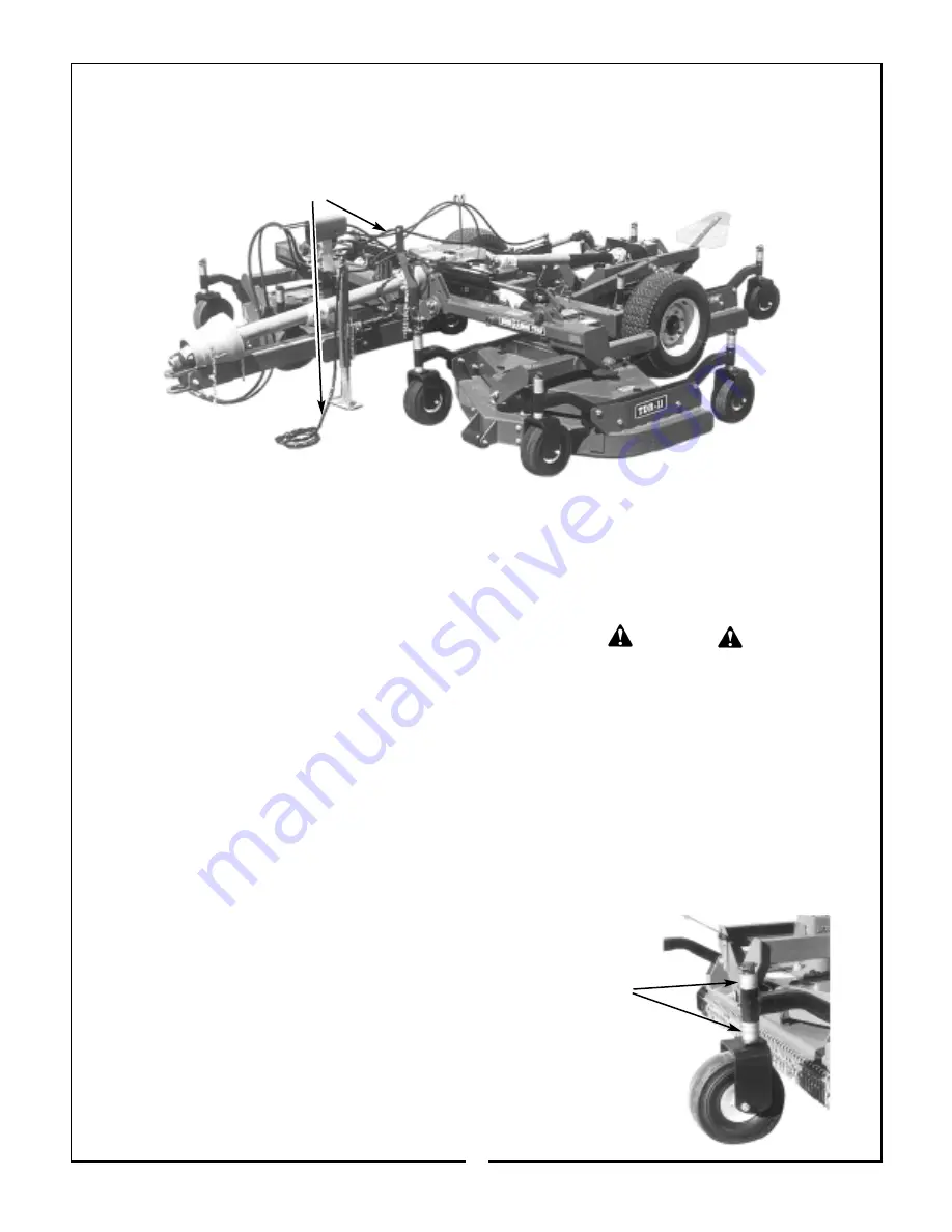
F. Route control chain to convenient location and
fasten to tractor. Be sure excess slack is removed
from the chain to avoid entanglement with tractor
tires or other moving parts. Make sure latch locking
pins are in the stored positions so that latches can

be released by pulling the chain.(Refer to  Figures
3-3 and 3-4)

G. Attach driveline to tractor . Pull on each drive-

line section to be sure that yoke locks into place.

H. Securely attach safety tow chain to tractor.

Figure 2-3         Control Chain

SECTION III

OPERATING INSTRUCTIONS

3-1 GENERAL SAFETY

Only qualified people familiar with this operator’s
manual and tractor operator’s manual should oper-
ate this machine. Operator should wear hard hat,
safety glasses and safety shoes. The operator
should read, understand and practice all safety mes-
sages shown on the caution, warning and danger
decals affixed to the mower to avoid serious injury or
death. It is recommended that tractor be equipped
with Rollover Protective System (ROPS) and a seat
belt be used. Before beginning operation, clear work
area of any objects that may be picked up and
thrown. Check for ditches, stumps, holes or other
obstacles that could upset tractor or damage mower.
Always lower mower to ground and allow blades to
come to a complete stop, set parking brake and turn
off tractor engine before leaving tractor operator’s
seat.

NOTE: Before initial operation the TDR should be con-
nected to the tractor for a 30 minute “run in” cycle.
During the “run in” phase, the tractor should be operated
at only half throttle. The “run in” phase will allow belt
warm-up and stretching before initial operation. After the
30 minute “run in” cycle is complete, ALL belts should
be inspected for proper tension and if adjustments are
necessary, refer to Maintenance Section.

3-2 CUTTING HEIGHT ADJUSTMENT

The mower should be operated at the highest posi-
tion that will give desired cutting results. This will
help prevent blades from striking the ground, reduc-
ing blade wear and undue strain on the machine.
Cutting too much material may leave excess clip-
pings on the surface.  The more frequently the grass

is mowed, the better the effect will be.

A. Raise mower off ground enough to remove

caster.

B. Remove pin securing caster stem to caster arm.

Remove caster stem from caster arm.

C. Place amount of spacers on caster stem to

give desired cutting height. With no spacers on the
bottom, a 3/4”  cutting height is given. (Figure 3-1)

D. Reinstall caster stem into caster arm. Place

remaining spacers on caster stem above caster arm
and install pin to retain.

E. Repeat operation for all caster wheels. Make 

certain all wheels are adjusted to the same height.

THE MOWER CAN FALL FROM HYDRAULIC
SYSTEM FAILURE. TO AVOID SERIOUS
INJURY OR DEATH, SECURELY SUPPORT
MOWER BEFORE WORKING UNDERNEATH.

WARNING

Figure 3-1

Caster Wheel

Spacers

9

Summary of Contents for TDR-11

Page 1: ...BUSH HOG OPERATION MAINTENANCE 4 00 Operator s Manual Tri Deck Finishing Mower TDR 11 300 Part No 50025363 ...

Page 2: ...ch are manufactured with the same precision and skill as our original equipment Our trained service personnel are well informed on methods required to service Bush Hog equipment and are ready and able to help you Should you require additional information or assistance please contact us YOUR AUTHORIZED BUSH HOG DEALER BECAUSE BUSH HOG MAINTAINS AN ONGOING PROGRAM OF PRODUCT IMPROVEMENT WE RESERVE T...

Page 3: ...t and to have any part s repaired or replaced when continued operation would cause damage or exces sive wear to other parts or cause a safety hazard It is the Retail Customer s responsibility to deliver the product to the authorized Bush Hog Dealer from whom he purchased it for service or replacement of defective parts which are covered by warranty Repairs to be submitted for warranty consideratio...

Page 4: ...y Bush Hog duty taxes charges for normal service or adjustment loss of crops or any other loss of income rental of substitute equipment expenses due to loss damage detention or delay in the delivery of equipment or parts resulting from acts beyond the control of Bush Hog THIS LIMITED WARRANTY SHALL NOT APPLY 1 To vendor items which carry their own warranties such as engines tires and tubes 2 If th...

Page 5: ...ion 5 All fasteners torqued to specifications given in Torque Chart 6 All decals in place and readable See decal page 7 Overall condition good i e paint welds 8 Operators manual has been delivered to owner and he has been instructed on the safe and proper use of the mower Dealer s Signature Purchaser s Signature THIS CHECKLIST TO REMAIN IN OWNER S MANUAL It is the responsibility of the dealer to c...

Page 6: ... the equipment safety signs These words are intended to alert the viewer to the existence and the degree of hazard seriousness This signal word indicates a potentially hazardous situation which if not avoided will result in death or serious injury White letters on RED This signal word indicates a potentially hazardous situation which if not avoided could result in death or serious injury It may al...

Page 7: ...ry passengers 6 Keep the area of operation clear of all persons particularly small children and pets The operator should cease mowing whenever anyone comes within the operating area 7 Clear the work area of objects which might be picked up and thrown 8 Use a piece of cardboard or wood rather than hands to search for hydraulic leaks Escaping hydraulic oil under pressure can penetrate skin If fluid ...

Page 8: ... not limited to instructions to Keep all guards in place when the machine is in operation Permit no riders on equipment Stop engine disconnect the power source and wait for all machine movement to stop before servicing adjusting cleaning or unclogging the equipment except where the machine must be running to be properly serviced or maintained in which case the employer shall instruct employees as ...

Page 9: ...el arrangement along with the flexi ble floating deck and the standard front and rear mounted rollers all work together to give an even cut and minimize scalping NOTE The inside rear wheel on the wing mower decks and both the front wheels on the rear mower deck are rigidly mounted and are not designed to caster Power from the tractor is transmitted through a telescoping driveline to a gearbox arra...

Page 10: ...NSTRUCTIONS WILL CAUSE DRIVELINE FAILURE AND POSSIBLE TRACTOR DAMAGE B Attach jackstand to frame of cutter Extend jackstand to support weight of frame C Connect clevis hitch to tractor drawbar using a Drawbar Height 8 12 1 2 12 1 2 17 Above 17 Clevis Tongue Adjustment Note Bolt Locations Pointed Out By Arrows SECTION II PREPARATION FOR USE NOTE Before operation service all locations outlined in Se...

Page 11: ...ine before leaving tractor operator s seat NOTE Before initial operation the TDR should be con nected to the tractor for a 30 minute run in cycle During the run in phase the tractor should be operated at only half throttle The run in phase will allow belt warm up and stretching before initial operation After the 30 minute run in cycle is complete ALL belts should be inspected for proper tension an...

Page 12: ... BE USED FOR ALL OPERATIONS LUG SPACING Figure 3 2 Make Sure Cylinders Are Fully Extended To Allow Decks To Float Wing CylinderLug Spacing Rear Cylinder Lug Space When mowing across slopes yawing or skewing may occur as the mower slips sideways which may cause streaking In this case mowing up and down slopes should be done to eliminate skewing 3 4 TRANSPORTING IMPORTANT Before folding for transpor...

Page 13: ...nt 3 Store cutter in a dry place 40 HOURS 1 Check belt for proper tension Refer to para graph 4 3 WARNING THE MOWER CAN FALL FROM HYDRAULIC SYSTEM FAILURE TO AVOID SERIOUS INJURY OR DEATH SECURELY SUPPORT MOWER BEFORE WORKING UNDERNEATH 4 2 LUBRICATION Figures 4 1A B C NOTE The multi purpose grease referenced in this section is an NLGI Grade 2 type grease Figure 4 2 shows the necessary position fo...

Page 14: ...t parts A Flip up black latches and remove right and left side shields To remove the outside shields on the wing cutter decks the wings must be in the folded position B Relieve spring tension by loosening the two 1 2 hex nuts on each spring adjustment rod Figure 4 2 C Remove old belt D Install new belt as shown below Also refer to the decal on underside of belt shield 1 Disconnect the adjustment r...

Page 15: ...ace blade s Streaking or Windrowing Possible build up of Clean cutter material under cutter Cutter not level See SECTION III Worn blades Replace blades Belt slipping Adjust belt per paragraph 4 3 Mowing across slopes Mow up and down slopes Noisy Cutter Loose components Check all bolts for tightness Low oil in gearbox Check oil per paragraph 4 2 Rapid Blade Wear Blade contacting Adjust cutting heig...

Page 16: ...for any of our products in the field at no charge Contact your authorized Bush Hog dealer for more information ALL AIR MUST BE PURGED FROM HYDRAULIC SYSTEM BEFORE ATTEMPTING TO RAISE OR LOWER THIS MACHINE REFER TO OPERA TOR S MANUAL FOR FUR THER DETAILS 94878 CAUTION ALL AIR MUST BE PURGED FROM HYDRAULIC SYSTEM BEFORE ATTEMPTING TO RAISE OR LOWER THIS MACHINE REFER TO OPERA TOR S MANUAL FOR FUR TH...

Page 17: ...DECALS CONTINUED 82683 83105 15 ...

Page 18: ...354 480 795 1077 1288 1745 1 11 16 1 1 8 12 UNF 397 538 890 1206 1444 1957 1 7 8 1 1 4 7 UNC 500 678 1120 1518 1817 2462 1 7 8 1 1 4 12 UNF 553 749 1241 1682 2013 2728 2 1 16 1 3 8 6 UNC 655 887 1470 1992 2382 3228 2 1 16 1 3 8 12 UNF 746 1011 1672 2266 2712 3675 2 1 4 1 1 2 6 UNC 870 1179 1950 2642 3161 4283 2 1 4 1 1 2 12 UNF 979 1327 2194 2973 3557 4820 Proper torque for metric fasteners used o...

Page 19: ...BUSH HOG L L C P O Box 1039 Selma AL 36702 1039 Telephone 334 874 2700 ...

Reviews: