17
2010 ST-104
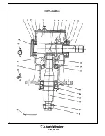
Gearbox Assembly Procedure
1. The output assembly goes into the housing first. If the upper bearing race has been pulled
out it must be pressed in. The lower bearing must be pressed onto the shaft before installa-
tion.
2. Once the output shaft is in place, install the upper bearing, shims, gear, and retaining nut.
3. The bearing preload is measured by rolling torque. The rolling torque should be between 6-
15 inch pounds. Adjust the retaining nut until you reach this rolling torque. Secure the re-
taining nut with the cotter pin.
4. The bearing race for the front bearing on the input shaft must be pressed in. Outer retaining
ring should be installed in the gearbox housing. Make sure the shims are installed between
the retaining ring and race as necessary.
5. Place the input shaft through the back of the gearbox while holding the gear in place. Slide
the shaft through the gear and press into the front bearing. Ensure the shaft to bearing retain-
ing ring is installed on the front of the input shaft. Install the gear to shaft retaining ring.
6. Press bearing onto the back of the shaft. Be sure to replace any shims that were removed
during disassembly. Press race partway into the back of the gearbox housing. Install the cap
on the back of the housing using the appropriate gasket and tighten the bolts to 38 ft-lb.
7. Check contact pattern of gear set with marking compound. Contact is to be in the central
toe area of the gear teeth with a minimum 50% tooth height and 50% tooth length in con-
tact. The back lash should be between 0.006‖ and 0.022‖ when measured at the pitch diame-
ter of the gear set. If the gear mesh or back lash are incorrect use shims reposition the gears.
8. The bearing preload is measured in the same manner as for the output shaft. The rolling
torque should be between 11-25 inch pounds. Install thicker gaskets to decrease the rolling
torque and thinner gaskets to reduce the rolling torque.
9. Once the preload is set, install the output spacer, seal, retaining ring, and seal protector. In-
stall the input seal in the housing. Remove the blank cap and apply sealant to the gaskets
and replace the cap. Torque the bolts back to 38 ft-lb.
10. Replace the inspection cover on the top of the gearbox and torque the bolts to 20 ft-lbs.
11. Fill the gear box with the recommended lubricant in an upright position similar to the
mounting position. Fill the gearbox to the level plug.
Summary of Contents for ST-104
Page 1: ...2010 ...
Page 4: ...4 2010 ST 104 Safety Section ...
Page 12: ...12 2010 ST 104 General Maintenance Tips ...
Page 19: ...19 2010 ST 104 Parts book ...
Page 22: ...22 2010 ST 104 3869 Gear Box ...
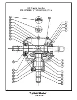
Page 24: ...24 2010 ST 104 2033 Transfer Gear Box USE NUMBER 0 WEIGHT OIL ONLY ...
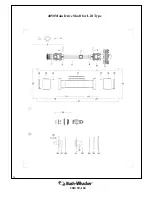
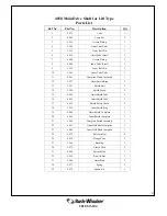
Page 26: ...26 2010 ST 104 4050 Main Drive Shaft for Lift Type ...
Page 36: ...36 2010 ST 104 ...
Page 37: ...37 2010 ST 104 Optional Equipment and Other Items not Illustrated ...
Page 42: ...42 2010 ST 104 4059 Complete Drive Shaft For Pull Type ...
Page 44: ...44 2010 ST 104 5038 Constant Velocity Drive Shaft ...
Page 52: ...52 2010 ST 104 Offset Adapter Assembly ...
Page 58: ......
Page 59: ...59 2010 ST 104 Notes ...


