background image


INSTALLATION IN A CAVITY WITH THE MOUNTING KIT 

For cavity installation we recommend allowing a minimum 5mm gap in width and height for ease of 
installation. A minimum gap of 50mm is recommended for the rear. Refer to the following table for the 
recommended cut-out dimensions.


MODEL 

CUT-OUT CAVITY DIMENSIONS (MM) 

WIDTH


DEPTH


HEIGHT


DC190L 

605 

575 

1385 

 
VENTILATION 

Two vents need to be provided from the rear of the fridge cavity to the outside environment, or to the general 
area where the fridge is located. The vents should be located at the bottom and top of the fridge cavity and 
have a free cross section of approximately 600cm

2

 each. Please note a 500cm x 250cm vent provides 

approximately 600cm

2

 of free air flow (not 1250cm

2


MOUNTING KIT 

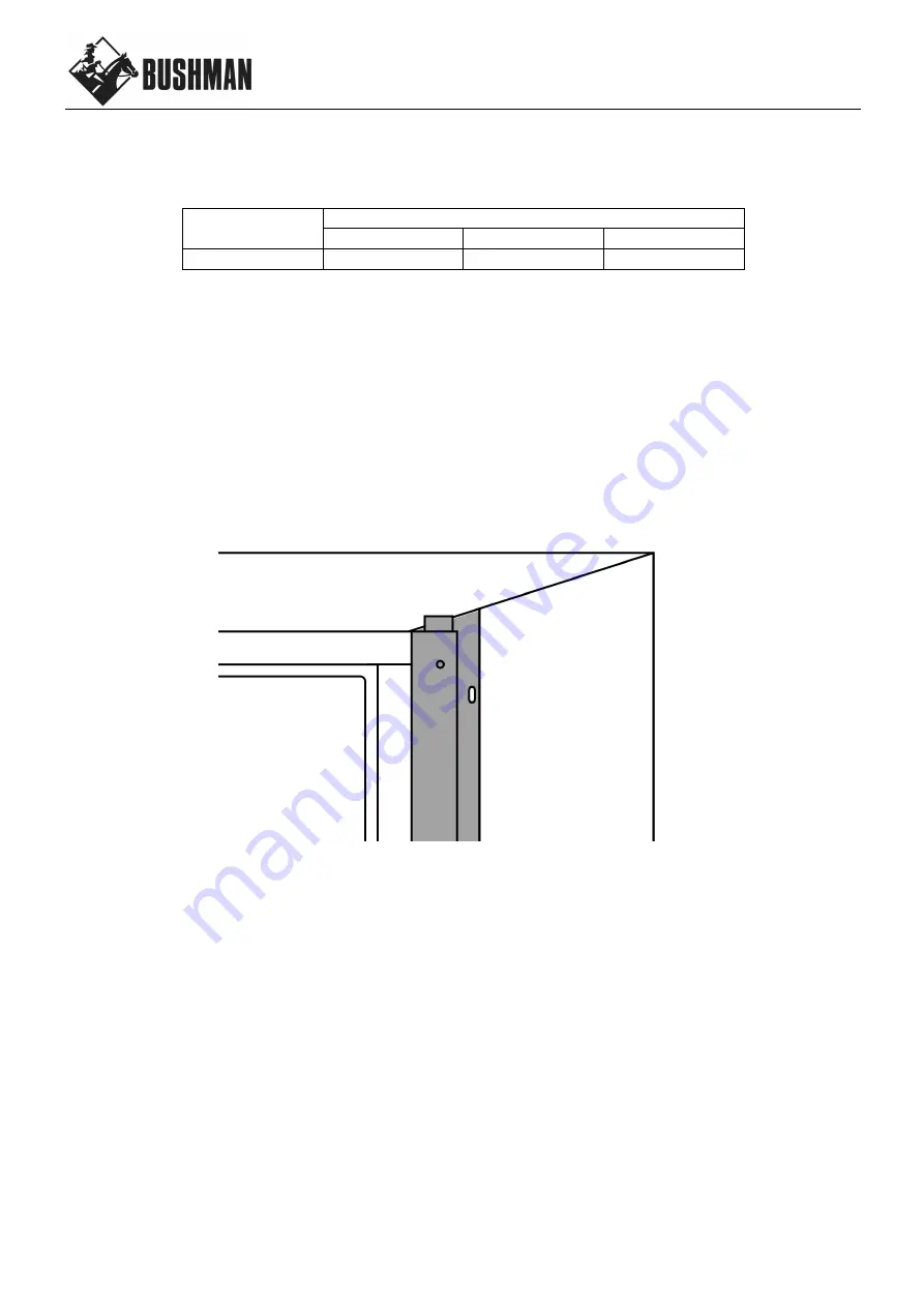
The mounting kit is affixed to the sides and top of the fridge cabinet using the screws provided. 
 

1.


There are 2 x side pieces. Each piece is slighlty different. Position the side pieces so they are flush with 
the front edge of the fridge cabinet, and so that the small tab is located at the top, as follows: 


2.


Carefully mark the position of each of the 4 holes in the mounting kit on the side of the fridge cabinet. 

3.


Remove the side pieces. 

4.


Drill 2mm pilot holes 5mm deep through the sheetmetal where marked. 

5.


Reposition the side pieces and screw to the fridge cabinet using the 8 screws provided. Do not over 
tighten. 

6.


There are 2 x top pieces. Each piece has a slightly bigger cut-out on one side. The larger cut-out goes 
over your top hinge plastic cap. Choose which piece you need depending on which side you have your 
hinges and discard the other. 

7.


Position the top piece so it is flush with the front edge of the fridge cabinet and carefully mark the position 
of the holes. 

8.


Remove the top piece and drill 2mm pilot hole 5mm deep through the sheetmetal where marked. 

9.


Reposition the top piece and screw to the fridge cabinet using the 2 screws provided. Do not over 
tighten. 

10.


Your fridge is now ready to be moved into your cavity. 

11.


We do not supply screws for affixing the mounting kit to your cavity, please choose screws of the correct 
type for the material your cavity is made from. 


Summary of Contents for DC190-L

Page 1: ...User Manual Operating Instructions DC190L CARAVAN MARINE RV OFFGRID ...

Page 2: ...t be completed by a suitably trained professional only POWER SUPPLY Your fridge must be connected to a stable and regulated 12 V or 24 V DC power supply only The compressor will automatically detect which voltage is present adjust accordingly If you are using a generator or other power supply the output must be a pure sine wave Any fluctuations in generator current may damage the compressor WIRING...

Page 3: ... of the fridge cabinet and so that the small tab is located at the top as follows 2 Carefully mark the position of each of the 4 holes in the mounting kit on the side of the fridge cabinet 3 Remove the side pieces 4 Drill 2mm pilot holes 5mm deep through the sheetmetal where marked 5 Reposition the side pieces and screw to the fridge cabinet using the 8 screws provided Do not over tighten 6 There ...

Page 4: ...e thermostat up from there if the fridge is not reaching 4 C Always use the lowest number possible Do not use setting 7 EQUALISING THE FRIDGE During the first 24 hours of operation your compressor will operate for longer than usual This process allows the internal air temperature food drinks condenser and insulation to equalise ENERGY SAVING TIPS Have a much ventilation as possible the more the be...

Page 5: ... fridge cabinet Only tighten screws finger tight 8 Align the freezer door until it is square with the fridge cabinet by twisting the door into position and manipulatin the postion of the top and middle hinges 9 Tighten top hinge screws fully 10 Align the main door until it is square with the fridge cabinet also by twisting the door into position and manipulatin the postion of the bottom and middle...

Page 6: ... the back of the fridge This is a normal part of the operation of a low power cooling system However it should build up slowly over many weeks Excessive ice build up is a problem as the ice eventually insulates the cooling element and hinders the fridge s ability to cool In this instance turning the thermostat up to flat out 7 will cause ice to build up even faster Therefore slowing the ice build ...

Page 7: ...6 V 10 9 V 24 V 21 3 V 22 7 V RED ERROR LIGHT There is a red LED light just to the LHS of the compressor If you are experiencing any problems with your fridge first check to see if the LED is blinking The number of blinks corresponds to the following error codes ...

Page 8: ...8 ...

Page 9: ...9 ...

Page 10: ...shman facility are not covered under this warranty However this warranty covers shipping charges related to returning the repaired product to the customer This warranty does not apply to damage or wear to the product caused by accident abuse misuse neglect unauthorized alteration or repair or if the product was not used in accordance with Bushman printed installation and operating instructions To ...

Page 11: ...11 NOTES ...

Page 12: ...12 NOTES For after sales service and enquiries please contact BUSHMAN FRIDGES 3 Contour Close Research VIC 3095 03 8080 9990 info bushman com au ...

Reviews: