Chapter 5
Operator
Instructions
Page 2-2
The BCB is also equipped with six LEDs. This can be used for troubleshooting the system.
The description of each LED can be seen in
Table 2-1:
Base Control Board LED Descriptions
LED
Color
Description
D2
Yellow Indicates a start pulse is being sent to an upstream and downstream unit. Normally
OFF. ON only during pulse duration (when an upstream, downstream, or the base
Start is pressed).
D3
Green Indicates a stop pulse is being sent to an upstream and downstream unit. Normally
ON. OFF only during pulse duration (when an upstream, downstream, or the base
Stop is pressed).
D4
Green Indicates the base is running. ON if the base is running, OFF if the base has
stopped.
D31
Green +12 VDC is being supplied to the board. Will not indicate a blown fuse. Normally
ON.
D33
Yellow Indicates a start input is received. Normally OFF. ON as long as a start input is
received.
D34
Red
Indicates a stop input. This signal will override any start signals. The base will not
run as long as this light is ON and it will not send any start signals to upstream or
downstream units. This LED is normally OFF.
Buskro Ltd.
BK760 / BK76IB Inkjet
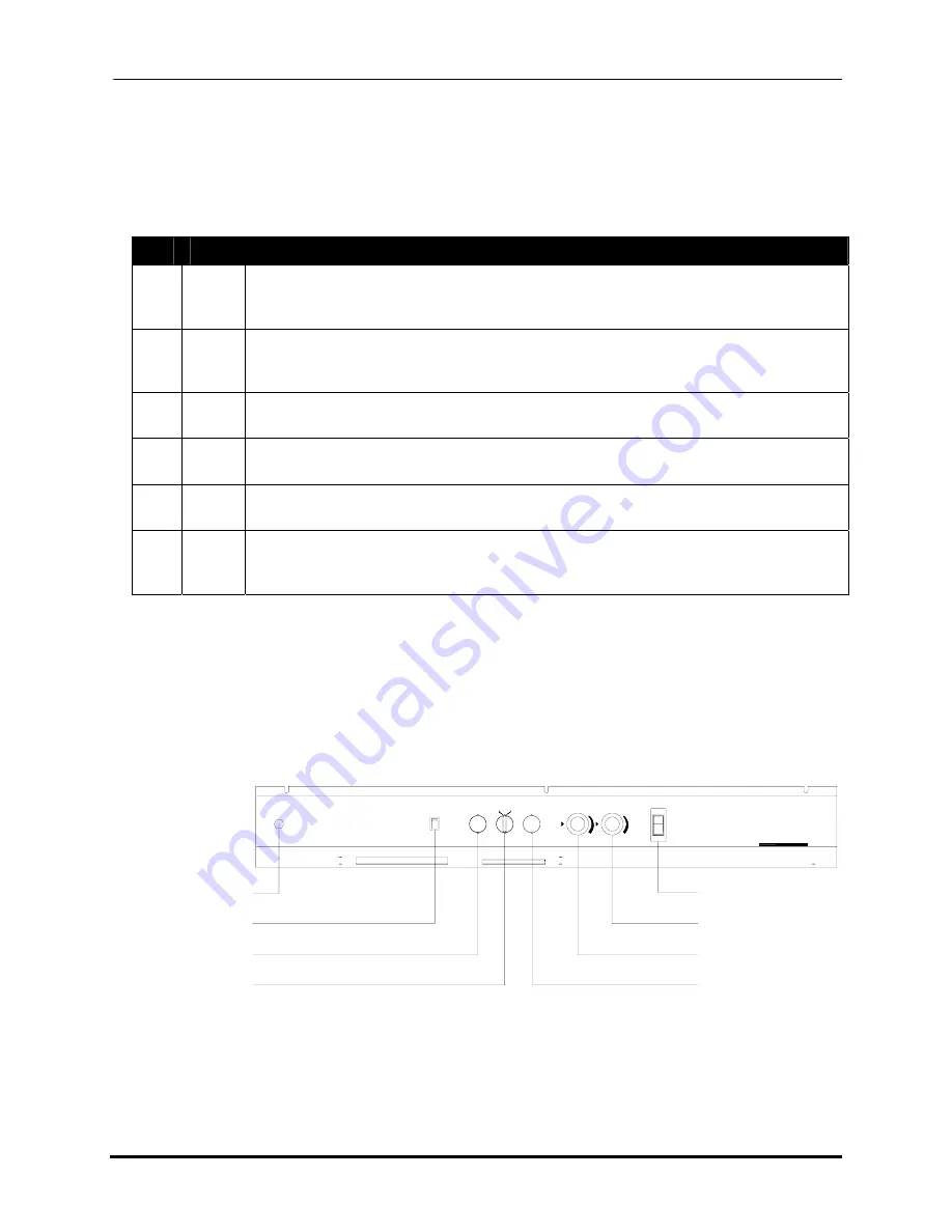
2.2 Instrument Panel (Main Control)
The main controls for the base are found on the instrument panel located at the front of the
Figure 2-2:
Base Instrument Panel
Jog
System
Feed Enable
START
Conveyor
PRODUCTION CONTROL
Run
STOP
Base
POWER
BUSKRO
Power Rocker Switch
Conveyor Speed Dial
Production Speed Dial
Stop Pushbutton
Optional Speed
Control Board Control
Auxiliary Feeder
Rocker Switch
Start Pushbutton
Jog/Run Selector


