3. Power down the host system.
4. Referring to your computer owner‘s manual, open
the case to gain access to the motherboard and ex-
pansion slots.
Step 2. Setting the SCSI Device ID
Each SCSI device must be assigned a unique SCSI ID
ranging from 0 through 7. Most SCSI peripheral devic-
es are shipped with a pre-assigned SCSI ID. Your
Logic adapter is set to SCSI ID 7 by default.
Note: The SCSI for your boot drive must be lower than
other drives. BIOS scans from ID 0
the boot drive.
If needed, change the SCSI ID for the peripheral devic-
es as recommended in the owner’s manual. To change
the adapter’s SCSI ID, use the
Host Adapter SCSZ ID
op-
tion on the AutoSCSI Configuration Menu (Step 7).
Step 3. Terminating SCSI Devices
The first and last SCSI devices connected together on a
SCSI bus must have terminators installed or enabled.
Terminators, which can be connected to either SCSI de-
vices or SCSI cables, are required for reliable operation
of the SCSI bus. If more than two SCSI devices are con-
nected in a SCSI daisy chain, you must remove the ter-
minators on the middle device(s).
If the BT-747C is not being installed at either end of the
SCSI bus, disable its terminators by using the
Adapter
SCSI Terminators ON
option on the AutoSCSI Configu-
ration Menu (see Step 7).
Step 4. Installing and Cabling the Adapter
Before installing the adapter, you must check that the
jumper cap is installed on
This jumper enables
communication with the floppy drive.
1.
2.
Remove the mounting screw and the existing
bracket from the rear panel behind the 32-bit slot
where you want to install the BT-747C.
Press the BT-747C downward into the selected
bit slot, align the mounting bracket, and reinstall
the mounting screw. Make sure that the board is
properly seated in the slot.
3.
4.
5.
6.
7.
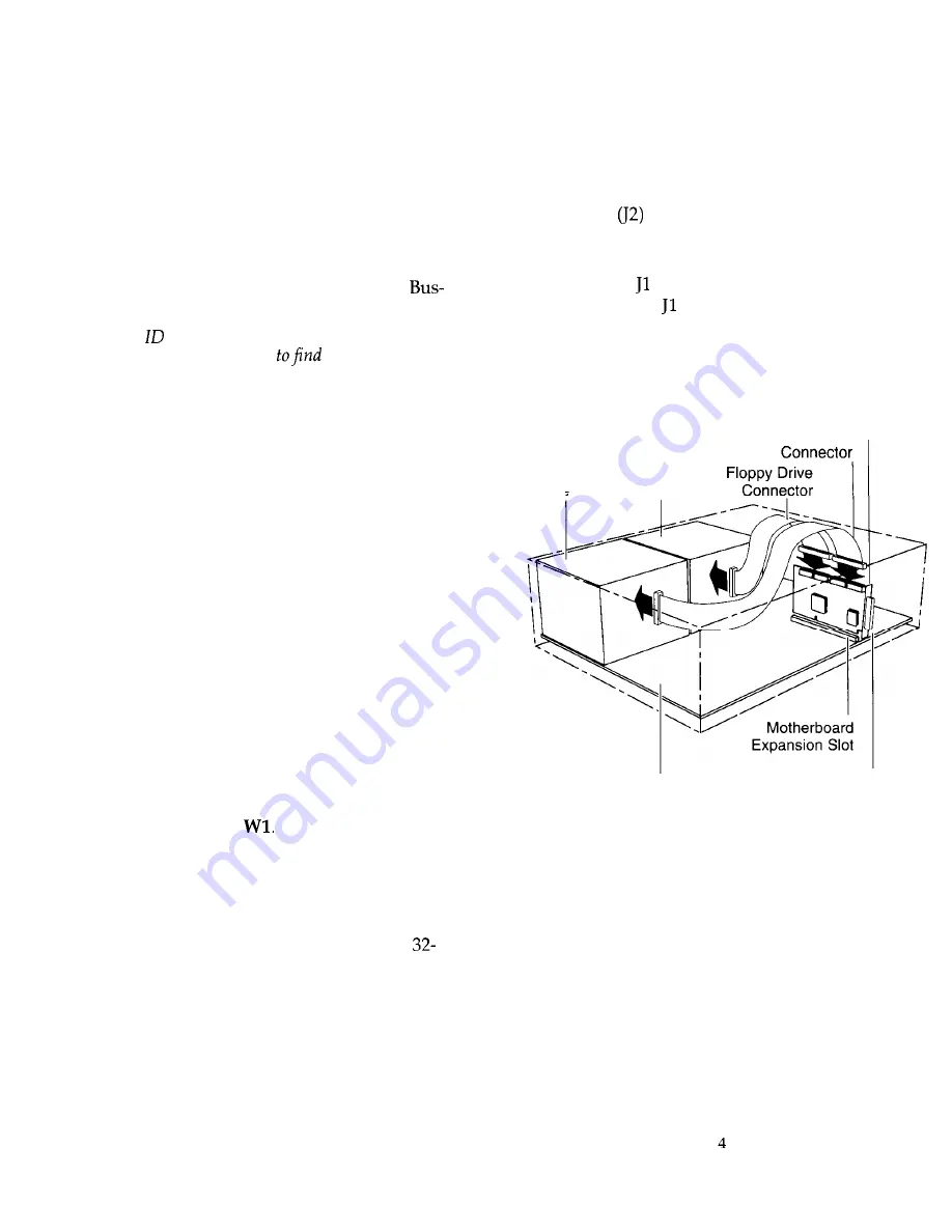
Connect the 50-pin SCSI cable to the adapter’s sin-
gle-ended SCSI connector, J3, attaching the other
end to the SCSI device connector.
If connecting to a floppy drive, insert the 34-pin
floppy cable from the floppy drive into the floppy
connector
(BT-747C only).
Insert the optional four-pin header connector for
the drive activity LED on the front panel of the host
to connector on the BT-747C. This connector may
be plugged into either way.
Verify that all connections are secure.
Reattach and close the cover of the host computer
as described in the system owner’s manual.
BT-747C
Internal
SCSI
Drive
Floppy internal SCSI
Disk
Drive
System
External SCSI
Motherboard
Connector
Figure 2. BT-747C Installation
Step 5. Updating System CMOS
1.
Once hardware installation is complete and the host
computer is reassembled, power up the system.
2. Run SETUP and configure the host CMOS RAM op-
tions. Set the drive type option for the SCSI drive to
No Hard Drive Installed.
3. Reset the system to activate your SETUP changes.


