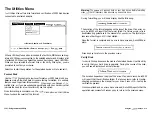
Configuring the Board Jumpers
Installing the Adapter
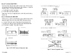
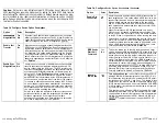
and JP2 select a specific adapter BIOS address for the BT-956X. They are
required where the
motherboard does not offer BT-956X support. Be-
fore proceeding, read Appendix A, “Configuration for Non-Conforming
Motherboards,” for a more detailed discussion on using these jumpers
and other configuration needs.
By default the board is configured without jumpers, assuming mother-
board support for automatic adapter configuration.
The following table shows possible
JP2 options.
BIOS Address
O N
OFF
JP2
ON
O N
O N
OFF
System BIOS
OFF
OFF (default)
ON installed; OFF not installed
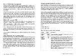
Caution: You may use
any combination of two
connectors, however, you
cannot attach devices to all three
connectors at the same time.
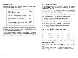
Don’t perform the following steps unless you have already:
Verified SCSI device
Properly set SCSI termination
n
Configured jumpers
2.
Internal
SCSI
Connector
Internal SCSI
68-Pin Connector
External SCSI
Connector
PCI System
Motherboard
Internal SCSI
Drive
Front Panel
LED
LED Connector
BT-956C
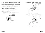
Figure 2-4. Adapter Installation
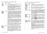
When you are ready to begin, power down the host system.
Referring to your host system owner’s manual, open the case to gain ac-
cess to the motherboard and expansion slots.
If the computer has been on, wait a few minutes until the power supply
case has cooled down inside the computer. If the power supply case is
cold, touch it to discharge any static electricity that may be on your
clothes or body.
2-8
installation
Installation
n
2-9
Summary of Contents for BT-956C
Page 1: ...m w h 0 0 0 m z n ...

