3.
4.
If another board has been installed, remove all connecting cables to the
board and then lift it out of the host computer.
To install the adapter card, remove the mounting screw and the existing
bracket from the rear panel behind the selected
slot.
Note:
The BT-956X can only be installed in a master slot, not a slave slot. Refer
to your system documentation to determine the correct slot for installation.
5.
Press the BT-956X downward into the selected
slot, align the
mounting bracket, and reinstall the mounting screw.
Caution:
Make sure that the board is properly seated in the slot.
6.
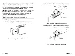
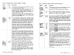
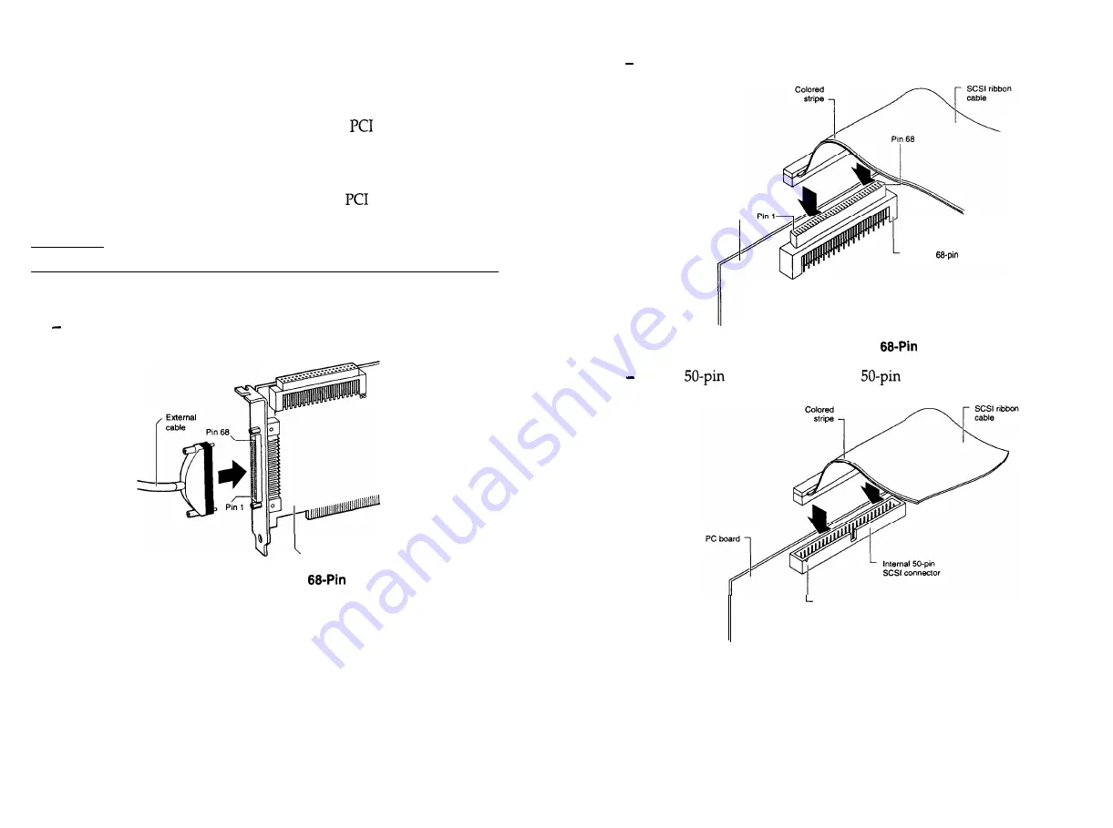
Attach the appropriate cabling:
Use 68-pin cabling to attach to the external 68-pin connector.
PC board
Figure 2-5. Cabling the External
Connector
Use 68-pin cabling to attach to the internal 68-pin connector.
PC board
1
Internal
Wide SCSI connector
Figure 2-6. Cabling the Internal
Connector
Use a
cable to attach to the
internal connector.
Pin 1
2-10
n
Installation
Figure 2-7. Cabling the Internal SO-Pin Connector
Installation
n
2-11
Summary of Contents for BT-956C
Page 1: ...m w h 0 0 0 m z n ...

