7.
8.
9.
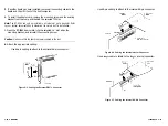
Before plugging in cable connectors, check that the
mark molded
on the connector or the colored stripe on the cable (indicating the loca-
tion of Pin 1) matches Pin 1 of the connector on the board.
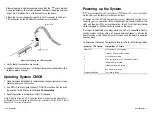
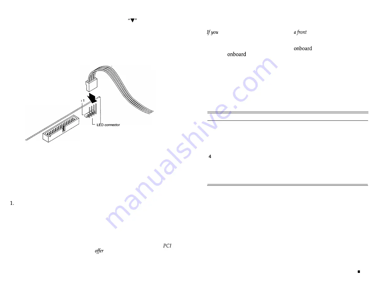
Attach the four-pin header drive activity LED connector to the 4-pin
LED connector on the BT-956X. This connector is reversible.
r
LED cable
Pin
Figure 2-8. Cabling the LED Connector
Verify that all connections are secure.
Reattach and close the cover of the host computer as described in the
system owner’s manual.
Updating System CMOS
2.
3.
Once hardware installation is complete and the host computer is reas-
sembled, power up the system.
Run SETUP and configure the host CMOS RAM options. Set the drive
type option for SCSI drive to No
Hard Drive Installed.
Reset the system to activate your SETUP changes.
Note: Additional system CMOS configuration may be required where the
motherboard is not compliant and does not
support for the BT-956X. Refer to
Appendix A for more information.
2-12
n
Installation
Installation
2-13
Powering up the System
have connected the LED connector to
panel LED, you will be able to
see the activity on the adapter’s fault/status indicator.
At power up, the LED turns on and an
diagnostic routine is run
to verify
operation. If the diagnostics find no malfunctions, the
LED will then go off. In normal operation, the LED will be illuminated
when command or SCSI bus activity occurs on the board.
If an error is detected by the diagnostics, the LED will repeatedly flash a
specific number of times, with a long pause between flashes, to indicate the
board function which failed. This will continue until the board is powered
down or reset.
To determine the cause of a diagnostic failure, refer to the following table:
Number of LED Flashes
Interpretation of Failure
Always On
host adapter is not operating
1
Firmware ROM checksum failure
2
Local RAM test failure
3
SCSI controller chip or SCSI interface failure
Internal data bus failure
5
Internal address bus failure
6
Bus master chip failure
Constantly Flashing
Term power failure
Summary of Contents for BT-956C
Page 1: ...m w h 0 0 0 m z n ...

