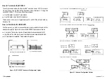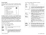
Summary of Configuration
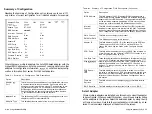
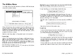
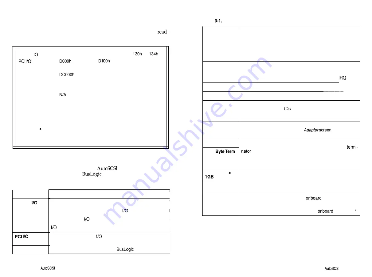
Selecting the Summary of Configuration option allows you to see a
only display of current configuration for all installed adapters. For example:
Adapter Port
330h
334h
230h
234h
Port
Adapter Type
BT-956C
BT-956C
BIOS Address
- -
Interrupt Channel 11
12
DMA Channel
None
None
DMA Xfer Rate
N/A
Adapter ID
7
7
SCSI Parity
On
On
Low Byte Term.
On
On
High Byte Term.
On
On
DOS Space
1
GB
No
No
Firmware Revision
4.00
4.00
BIOS Revision
4.90
- -
Where there are multiple adapters, the AutoSCSI-based adapter with the
highest BIOS address controls the process of reading data from other
adapters for configuration information.
will also display config-
uration information from earlier
host adapters.
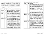
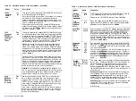
Table 3-1. Summary of Configuration Field Descriptions
Option
Description
Adapter
Port
Port
This field shows the base address of the registers the host uses
to communicate with the host adapter. Each board within the
same host system must have a unique
port address to pre-
vent hardware conflicts. On PCI adapters, the host system’s
BIOS assigns the
port address during the boot sequence.
Each board within the same host system must have a unique
port address to prevent hardware conflicts.
This field shows the PCI
port address assigned to the host
adapter by the PCI motherboard BIOS.
Adapter Type
This field identifies the model of the
host adapter.
Table
Summary of Configuration Field Descriptions (Continued)
Option
BIOS Address
Description
This field displays the SCSI adapter BIOS starting address in
host memory. Where multiple adapters are installed, the primary
adapter must have BIOS enabled. It is suggested that the BIOS
on the remaining adapters be disabled but it is not required as
long as you ensure that the BIOS addresses don’t conflict.
Interrupt
Channel
This field shows the hardware interrupt line (IRQ) number that
the adapter uses to generate interrupts to the host. The adapter
issues an interrupt whenever it requests attention from the host.
On PCI adapters, the host system’s BIOS assigns the
value.
DMA Channel
This field does not apply to this product.
DMA Xfer Rate
This field does not apply to this product.
Adapter ID
This field displays the SCSI ID of the adapter on the SCSI bus.
There are sixteen SCSI
(O-15) on a wide SCSI bus. To
change this value, use the option on the
Configure Adapter
screen.
SCSI Parity
This field indicates whether parity on the SCSI bus is turned on
or not. You may use the
Configure
option to turn
the SCSI parity detection on or off.
Low Byte Term
These fields indicate whether the adapter’s termination is turned
on or not. SCSI devices are daisy-chained together and a
High
is required at each end of the chain. To determine your ter-
mination requirements, see “Terminating SCSI Devices” in
Section 2. To change this value, use the options on the
Configure
Adapter
screen.
DOS Space
This field displays whether this option is turned on or off. How
this value is set depends on DOS size requirements and the boot
requirements of other operating systems. See the detailed de-
scription of this option under “Advanced Configuration” later in
this section.
Firmware
This field shows the host adapter’s
firmware revision
Revision
level.
BIOS Revision
This field displays the revision level of the
BIOS.
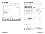
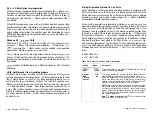
Select Adapter
Where multiple adapters are installed, use this option to select the adapter
to be configured. When you select this option, you will see a display listing
all the adapters in the system. Select the desired adapter by using the Up
or Down arrow keys. Note that the current adapter is indicated by an as-
terisk. It is also always displayed at the bottom of the screen.
3-4
n
Using
the
Utility
Using the
Utility
n
3-5
Summary of Contents for BT-956C
Page 1: ...m w h 0 0 0 m z n ...

