background image

Caution: 

Data errors may indicate external SCSI cables do not adhere to new

SCSI specifications requiring higher quality cables for faster SCSI data transfer

rates 

 ribbon type is not a problem). Attached devices may not be prop-

erly terminated or may require active termination at the device end on the SCSI

cable. 

 adapters include active termination when the Host Adapter SCSI

Terminators option is enabled.

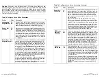
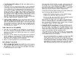
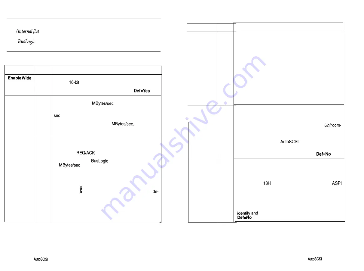
Table 3-4. Configure Device Option Descriptions

1

Option

Value

Description

Yes

Negotiation No

By default the Enable Wide Negotiation option is enabled,

allowing 

 data transfers on the SCSI bus. Disable this

option only if you have an older eight-bit SCSI device that is
unable to respond to wide SCSI negotiation. 

Enable Fast

Yes

Transfer

No

Many devices are capable of transferring data across the
SCSI bus at 10 to 20 

 Enabling this option can

significantly increase performance in some applications if
the attached device can also support the faster 20 MBytes/

 data rate. This option works together with the 

Enable

Sync Negotiation 

option. Yes enables the adapter to nego-

tiate a transfer rate from 20 to 8 

 No limits the

adapter to negotiating a transfer rate from 10 to 8 MBytes/
sec. 

Def=Yes

Enable Sync

Yes

Negotiation No

Use this option to enable or disable the synchronous data

transfer negotiation between the adapter and each SCSI
device connected to the SCSI bus. The SCSI protocol de-
termines the 

 offset and the data transfer rate for

synchronous data transfers between an initiator and a tar-
get on the SCSI bus. 

 boards are capable of up to

20 

 SCSI data transfers. However, the actual

data transfer rate is determined by the SCSI target device if
the device has a transfer rate lower than that of the adapter.

This option is offered because some classes of SCSI devic-
es do not support synchronous data transfer. An attempt to
perform this ne otiation protocol may result in an unpredict-
able response rom the SCSI device. Check your SCSI 
vice manual before enabling this option.

Select Yes to allow the adapter to initiate synchronous ne-
gotiation; select No to allow the target device to initiate syn-

chronous negotiation. If the target doesn’t initiate
synchronous negotiation then data will transfer across the
SCSI bus in asynchronous mode. Def=Yes

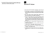
Table 3-4. Configure 

Device Option Descriptions (Continued)

Option

Enable Dis-

Yes

connection

N o

BIOS Sends
Start Unit
Command

Ignore in
BIOS Scan

Value

Yes

No

Yes

No

Description

Use this option to enable or disable SCSI disconnection on
each target device. This option allows a SCSI device to dis-
connect itself when the device is not ready for data transfer.
When multiple devices are connected to the same SCSI
bus, SCSI disconnection allows SCSI devices to perform
seek operations in parallel and thus improve overall SCSI

bus performance.

Higher Performance. In DOS applications only, perfor-
mance can be increased by disabling disconnection. This

should only be done when there is only one device attached
to the SCSI bus or only one device will be running at a time.

This option must not be disabled when running UNIX, Net-
Ware, OS/2 or other Non-DOS operating systems. Many
operating systems require this option to be enabled, even
with a single disk device attached to the SCSI bus, to pre-

vent the possibility of system failure. 

Def=Yes

This option allows you to identify the drives whose motor
spin-up is sequentially controlled by BIOS at power-up. This

prevents all drives from spinning up at the same time. Disk
drives often have a spin-up jumper that allows the user to
select 

Spin-up at Power-On 

or 

Spin-up with Start 

mand. This feature is only effective if BIOS is enabled. If
multiple adapters are installed, only the first BIOS needs to
be enabled to control this function across all adapters in-
stalled that also support 

 Yes allows BIOS to se-

quentially issue a Start Unit command at power-up. No
prevents BIOS from issuing this command (Devices are
normally enabled for 

Spin-up at Power-On.). 

This option allows you 

to boot from drives at any SCSI ID

address. BIOS will first attempt to boot from SCSI ID 0. If
this ID address is selected to be ignored then BIOS will at-
tempt to boot from SCSI ID 1 and so on. This feature is also

useful when you want to exclude a removable device from
BIOS interrupt 

 support. You must install the DOS 

driver to support any device that is selected to be ignored
by the BIOS scan.

This feature is only effective if BIOS is enabled. If multiple
adapters are installed, only the first adapter’s BIOS needs
to be enabled to control this function across all adapters in-
stalled that also support AutoSCSI. When No, BIOS will

 register the device at the specified SCSI ID.

3-10 

Using the 

 Utility

Using the 

 Utility 

3-11

Summary of Contents for BT-956C

Page 1: ...m w h 0 0 0 m z n ...

Page 2: ...ctor ic SCSI Host Adapter is shielded against the generation of ante with the application of Council Directive 89 336 EEC Article 4a Conformity is declared by the application of EN 55 022 1987 Class B CISPR 22 1985 BS 65271988 EN50082 1 GENERIC IMMUNITY STANDARD 1 IEC 801 2 1992 CRITERIA B 2 IEC 801 3 1992 CRITERIA A 3 IEC 801 4 1988 CRITERIA B 4 IEC 801 5 DRAFI 1993 CRITERIA B Co yright 0 Popyrig...

Page 3: ... Answers Appendix A Configuration for Non Conforming PCI Motherboards BIOS Address Configuration A 2 Handling Motherboard Variations A 3 Introduction The BusLogic BT 956C and BT 956CD BT 956X PC1 Wide SCSI Host Adapters are intelligent PC1 to SCSI bus master host adapters based on BusLogic designed universal ASIC technology Each provides a high per formance interconnection between the Peripheral C...

Page 4: ...erating parameters can be configured using the AutoSCSITM Util ity a menu based tool residing in the adapter s Read Only Memory ROM In addition to its simplified configuration AutoSCSI offers diag nostics and disk utilities Hardware Requirements Your PC1 computer needs n One available PC1 expansion slot master not slave for each BT 956X be ing installed w At least one 3 5 floppy drive n DC power f...

Page 5: ...ard disk drives BusLogic offers device drivers that support ASP1 Advanced SCSI Pro gram Interface for configurations where more hard drives are needed than your version of DOS can support BusLogic also offers CD ROM drivers for DOS and Windows If you are installing other types of devices under DOS and Windows such as a tape backup device or a scanner you will need to install additional drivers tha...

Page 6: ...sing 0 to 10 000 ft operating 0 to 15 000 ft non operating Interface Connections SCSI Internal 68 pin Wide SCSI connector 50 pin double row connector SCSI External 68 pin Wide shielded SCSI connector To From System PCI standard edge connector Installation This section details hardware installation See Chapter 3 for information on using AutoSCSI to configure adapter operating parameters What s Cove...

Page 7: ... items may be needed to assist with installing the adapter into your system n Small screwdriver w Small needle nosed pliers w Host system hardware manuals and manuals for the peripherals being installed Connecting Peripherals The following discusses considerations when connecting peripherals to your system Cabling You may need the following cables to attach SCSI peripherals to the adapt er n 6 pin...

Page 8: ...at the ends of the cable 16 bit The only time you may need to change the adapter s SCSI ID is when mul tiple adapters share the same SCSI bus To change your adapter SCSI ID use the Host Adapter SCSI ID option on the AutoSCSI s Configuration Menu Section 3 Using the AutoSCSI Utility 8 bit Off On Note BIOS looks for the boot drive by scanning devices according to their SCSI ID starting at SCSI ID 0 ...

Page 9: ...ata bits O 7 n High Byte The last two pairs of terminators terminate data bits 8 15 N All terminators installed Terminates all signals Low Byte Terminates data bits O 7 I All Terminates all signals High Byte Terminates data bits 8 15 Figure 2 2 BT 956CD Terminator Configuration Options Only one connector is used Onboard termination High Byte On Low Byte On BusLogic Host Adapter One 66 pin and the ...

Page 10: ...wo SCSI connectors however you cannot attach devices to all three SCSI connectors at the same time Don t perform the following steps unless you have already w Verified SCSI device IDS w Properly set SCSI termination n Configured jumpers zf needed 1 2 Internal SCSI 50 Pin Connector Internal SCSI 68 Pin Connector External SCSI 68 Pin Connector PCI System Motherboard Internal SCSI Drive Front Panel L...

Page 11: ...wnward into the selected PC1 slot align the mounting bracket and reinstall the mounting screw Caution Make sure that the board is properly seated in the slot 6 Attach the appropriate cabling Use 68 pin cabling to attach to the external 68 pin connector PC board Figure 2 5 Cabling the External 66 Pin Connector Use 68 pin cabling to attach to the internal 68 pin connector PC board 1 r Internal f38 p...

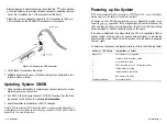
Page 12: ...T 956X Refer to Appendix A for more information 2 12 n Installation Installation w 2 13 Powering up the System lfyou have connected the LED connector to afront panel LED you will be able to see the activity on the adapter s fault status indicator At power up the LED turns on and an onboard diagnostic routine is run to verify onboard operation If the diagnostics find no malfunctions the LED will th...

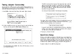
Page 13: ...play similar to the following during testing Testing DMA in memory range Segment Offset Performing Walking l s and O s on 6000H 4740H Test Loop 2 The display has a counter indicating the memory locations as they are be ing tested and the number of test loops completed If the test fails AutoSC SI shows the failing address value For example DMA test failed at the above address In case of a failure r...

Page 14: ...ed to change operating parameters if resource conflicts occur When further configuration is required use the AutoSCSI Utility as de scribed below Note While older BusLogic adapters installed in the host system are detected and appear in AutoSCSI screens they cannot be configured with AutoSCSI Note Some motherboards are not PC1 compliant and may not support the BT 956X Additional configuration may ...

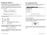
Page 15: ... Help screens Note that the currently selected adapter s I O port address where multi ple adapters are installed is always displayed at the bottom of the screen inside the angle brackets cc For example Current Adapter at IO Port 330h When you exit AutoSCSI after making configuration changes the system prompts you to reset your system The reboot allows changes to configura tion to become operationa...

Page 16: ...that the BIOS addresses don t conflict Interrupt Channel This field shows the hardware interrupt line IRQ number that the adapter uses to generate interrupts to the host The adapter issues an interrupt whenever it requests attention from the host On PCI adapters the host system s BIOS assigns the IRQ value DMA Channel This field does not apply to this product ___ DMA Xfer Rate This field does not ...

Page 17: ... applicable to this product _ Adapter SCSI ID 8 bit o 7 Use this option if you need to change the adapter s SCSI ID on the SCSI bus This ID should remain unchanged even 16 bit where there are multiple SCSI adapters unless the adapters o 15 are attached to a common SCSI bus cable Def 7 SCSI Parity O n Off This setting allows you to enable or disable parity checking by the adapter on the SCSI bus Di...

Page 18: ...ing Fast Transfer and Sync Negotiation Enable Sync Enable Fast Result Negotiation Transfer Yes Yes No No Yes Adapter initiates transfer rate negotiation starting at 20 M Bytes set No Adapter initiates transfer rate negotiation starting at 10 MByteslsec Yes No SCSI device may initiate negotiation for data transfer rates starting at 20 MByteskec i SCSI device may initiate negotiation for data transf...

Page 19: ...s in asynchronous mode Def Yes Table 3 4 Configure Device Option Descriptions Continued Option Enable Dis Yes connection No BIOS Sends Start Unit Command Ignore in BIOS Scan Value Yes No Yes No Description Use this option to enable or disable SCSI disconnection on each target device This option allows a SCSI device to dis connect itself when the device is not ready for data transfer When multiple ...

Page 20: ...r Yes or NC Use the Up and Down arrow keys to move to the desired option Pres ENTER to toggle between selections 1 Enable the 1 GByte option using the AutoSCSI utility 2 Run the DOS FDISK utility and delete all the partitions on the drive 3 Reboot the system so BIOS will use the new translation scheme 4 Run the DOS FDISK utility to create the 1 GByte partition 5 Run the DOS Format utility to high ...

Page 21: ... Multiple Operating Systems On One Drive When NetWare or other supported operating systems is combined with DOS on the same drive then the size and locations of any and all of the DOS partitions must not exceed the 1 GByte size limitation and or address boundary unless drivers which include support for 1 GByte translation are available for both operating systems When multiple operating systems are...

Page 22: ...ly the I irst two SCSI hard disks or removable drives If this option is enabled default BIOS will scan and support devices up to the highest target ID number on the SCSI bus During scanning BIOS skips IDS that do not have a target device present Def Yes Table 3 6 Advanced Options Field Descriptions Continued C C f t I I i 1 I I Iption nterrupt enerated or BIOS Zommand 310s pports loptical Irives S...

Page 23: ... drives Before formatting make sure that all necessary data is backed up on another drive During formatting you will see a display like the following Formatting Please wait for completion The duration of the format depends on the size of the drive If an error oc curs AutoSCSI will report that the format failed If a failure occurs refer to troubleshooting guidelines in the manuals for your drive Th...

Page 24: ...are completed refer to the following guidelines Check the Installation Procedures n Be sure all connectors are firmly seated n Check the orientation of the SCSI cable Be sure that Pin 1 on the cable matches Pin 1 on the adapter SCSI device connector n Check that the adapter and attached devices have unique SCSI IDS n Be sure that the SCSI ID for the boot hard drive is lower than any other drive BI...

Page 25: ...stics Menu to test the adapter s connectivity to the motherboard A device is not required to be attached to the adapt er s SCSI bus connector to run this test When successful this test indicates your system motherboard supports a Bus Master DMA mode of operation and can transfer data between your system memory and the SCSI adapter at 5 MBytes set or at the se lected DMA data transfer rate It also ...

Page 26: ... is not recognized verify that each device has a unique SCSI ID O 7 for bit devices O 15 for 16 bit devices The host adapter is set to SCSI ID 7 by default n Adapter fails to communicate with selected SCSI device Disable Fast Transfer RatelWide Negotiation Some SCSI devices may not be capable of negotiating a data transfer rate of 20 MBytes set If a device cannot support the higher rate it is supp...

Page 27: ...ded n Disable the Enable Disconnection option in AutoSCSI if running DOS with a single device attached to the SCSI bus Disable this option only when there is only one device attached to the SCSI bus or only one de vice will be accessed at one time Do not disable when running operat ing systems that support multitasking or advanced features such as Command Tag Queueing Caution Do not disable this w...

Page 28: ...ith the format C s option Note this will erase any data currently on your hard drive If the drive was previously used on another controller you may need to perform a low level format and then prepare the drive with DOS Fdisk and Format utilities If the mapping mode has been changed since the last hard disk partitioning perform another Fdisk and Format Q My system displays a Hard Disk Failure messa...

Page 29: ...copy of the BTDOSM SYS file version 2 0 and try it The original file may be corrupted Copies of this file can be obtained in our BBS Q Why I am getting slow transfer times with my new FAST SCSI 2 hard drives A Make sure the drive is jumpered FAST SCSI 2 and active termination Also check that the controller has both Synchronous Negotiation and Fast Data Transfer enabled Q Can I connect SCSI I and S...

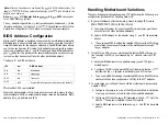
Page 30: ...otherboards One of the objectives of products designed under the Peripheral Compo nent Interconnect PCI Specification 2 0 is to offer a plug and play capabil ity simplified installation optimized host resources and automatic resolution of configuration conflicts Configuration and set up are per formed by the BIOS residing in the host system s motherboard BusLogic s PC1 adapters are designed to tak...

Page 31: ...s and IRQ Handling Motherboard Variations There are five general categories among PC1 motherboards Following are configuration guidelines for handling each kind 1 2 3 If your motherboard offers hardware jumpers to assign IRQ values IRQ9 IRQlO IRQll IRQ12 IRQ14 IRQ15 A B C Configure the jumper for one of these IRQ values as long as it does not conflict with other installed adapters Select a BIOS ad...

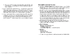
Page 32: ...ort Record on the back of this page before calling n BusLogic s Technical Support Bulletin Board System BBS is available 24 hours a day seven days a week It provides information on software updates and new releases technical bulletins and other information You may also leave your questions which will be answered within 24 hours The BBS can be reached at 408 492 1984 To access the BBS all you need ...

Page 33: ...c Product BusLogic Product No Serial Number Date of Purchase Firmware Version Number BIOS Version Number Purchased From Company Address Purchased By Name Title Company Address Telephone Fax About System Hardware Configuration System Manufacturer System Model and Speed System BIOS Manufacturer Memory in System Hard Drives on System About System Software Configuration Operating System Version Applic...

Page 34: ...c for repair which are out of the warranty period shall be at Customer s expense both to and from BusLogic Customer is expressly prohibited from issuing Debit Memos for material returned der the provisions of this warranty un BusLogic shall notify Customer in the event that the Products returned for repair are not in BusLogic s sole opinion within this Warranty condition and unless disposition ins...

Reviews: