6
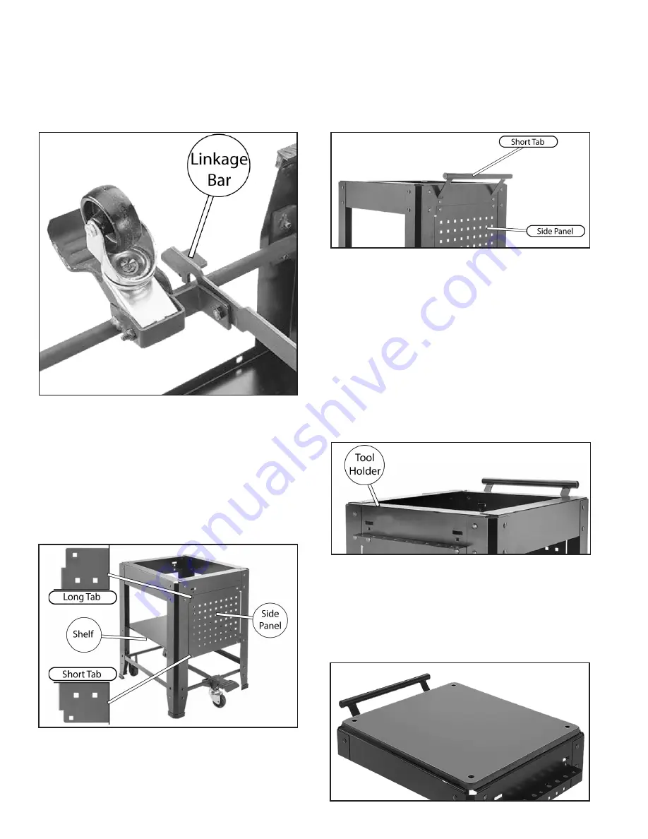
11. Connect the linkage bar to the pedal assem-
bly loosely using (1) M8-1.25 x 20 hex bolt
and (1) M8-1.25 lock nut to allow movement
of pedal.
12. Return the workshop table assembly back to
its upright position to attach bottom of side
panel to table assembly shelf using (2) M8-
1.25 x 12 carriage bolts and (2) M8-1.25 lock
nuts
13. Connect the handle to the top of the side
panel using (4) M8-1.25 x 12 carriage bolts
and (4) M8-1.25 lock nuts. Handle should be
installed on the same side as the foot pedal.
14. Repeat Step 12 to attach the other side panel
on the opposite side of the workstation as-
sembly.
15. Fasten the tool holder and top side panel us-
ing (2) M8-1.25 x 12 carriage bolts and (2)
M8-1.25 lock nuts.
16.Fasten the table top into place using (4) M8-
1.25 x 25 flat head screws and M8-1.25 hex
nuts.
Summary of Contents for B3620
Page 1: ...1 MODEL B3620 UNIVERSAL MOBILE WORKSHOP STAND USER MANUAL ...
Page 8: ...8 ...
Page 9: ...9 ...


