INSTRUCTION, USE AND
MAINTENANCE MANUAL
GB
Page 28 of 67
12.0 MACHINE SWITCHING ON AND OFF
BEFORE MACHINE SWITCHING
ON, MAKE SURE THE SMART
CARD (FIG. 17 REF. 3) FOR PRO-
GRAM ENABLING AND MEMORY
BANK IS INSERTED IN THE PRO-
VIDED READER, IN THE PC BACK
PART (SEE Fig. 17).
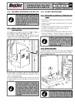
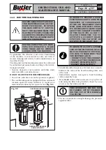
12.1 Smart card for program protection and
memory bank
All machines are equipped with a PC (
Fig. 17 ref. 1
)
with SMART CARD reader (
Fig. 17 ref. 2
).
This SMART CARD (
Fig. 17 ref. 3
), inserted in the
reader allows the functioning of the program itself and
enables access to vehicles DATABASE.
Fig. 17
Each machine is equipped with its own single SMART
CARD, , which can not absolutely be replaced by a smart
card of another machine.
When such SMART CARD, is removed or replaced, the
program displays an error message and does not allow
to carry on.
IN CASE OF SMART CARD MAL-
FUNCTION DURING PC SWITCH-
ING ON PHASE, CONTACT THE
MANUFACTURER, WHICH WILL
AUTHORIZE THE RETURN OF THE
FAULTY SMART CARD. IT WILL
BE REPLACED WITH A WORKING
ONE WITH THE SAME USB SERIAL
NUMBER.
13.0 USING THE MACHINE
13.1 Preliminary operations - Preparing the
wheel
• Remove the wheel balancing weights from both sides
of the wheel.
• Remove the valve stem and allow the tyre to com-
pletely deflate.
• Establish from which side the tyre should be de-
mounted, checking the position of the groove.
• Find the rim locking type.
• Try to establish the special types of wheels, such as
“EH2” and “EH2+”, in order to improve locking, bead
breaking, assembly and disassembly performances.
W H E N H A N D L I N G W H E E L S
WEIGHING MORE THAN 10 KG
AND/OR WITH A FREQUENCY
OF MORE THAN 20/30 WHEELS
PER HOUR, A LIFTING DEVICE
SHOULD BE USED.
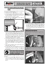
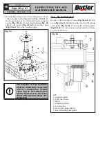
13.2 Wheel clamping
All wheels must be locked on the rubber plate (
Fig. 18
ref. 1
) through the central hole using the proper locking
ring nut (
Fig. 18 ref. 2
).
Fig. 18
IN CASE OF USE OF RIMS WITH-
OUT CENTRAL HOLE, IT’S NECES-
SARY TO USE THE PROPER FIX-
TURE (AVAILABLE ON DEMAND).
CAPTURE 4 - CAPTURE 4 FI
7104-M007-4_B


