INSTRUCTION, USE AND
MAINTENANCE MANUAL
GB
Page 40 of 67
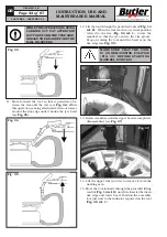
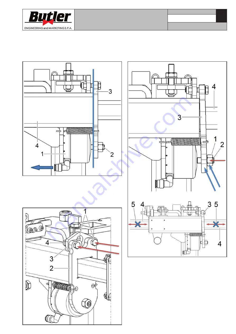
a. Blow off the compressed air from neck’s cylinder
(
Fig.
55 ref. 1
). Make neck (
Fig.
55 ref. 3
) reach
beat position again on the guide support surface
(
Fig.
55 ref. 4
), by turning the adjusting dowel (
Fig.
55 ref. 2
).
Fig. 55
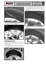
b. Completely screw fulcrum-type screw (or screws)
(
Fig.
56 ref. 1
) but without locking them, just mak-
ing them approach, setting a 0.1 ÷ 0.2 mm play
between neck (
Fig.
56 ref. 2
) and adjusting plate
(
Fig.
56 ref. 3
), positioning nut (
Fig.
56 ref. 4
) and
letting it rest completely onto adjusting plate.
Fig. 56
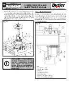
c. Slacken lock nut (
Fig.
57 ref. 1
) of adjusting
dowel (
Fig.
57 ref. 2
). Then, slacken dowel (
Fig.
57 ref. 2
) until neck (
Fig.
57 ref. 3
) strikes onto
arm (
Fig.
57 ref. 4
), that as a consequence results
clamped (
Fig.
57 ref. 5
).
Fig. 57
CAPTURE 4 - CAPTURE 4 FI
7104-M007-4_B


