INSTRUCTION, USE AND
MAINTENANCE MANUAL
Page 11 of 36
GB
10.0 ASSEMBLY AND PREPARATION FOR
USE
After having freed the various components from the
packing check that they are complete, and that there
are no anomalies, then comply with the following in-
structions for the assembly of the components making
use of the attached series of illustrations.
10.1 Assembly procedures
Remove the packaging and free the machine from the
wrapping. Lift the machine and position it on the floor.
10.2 Post assembly
In case the post is supplied demounted, proceed fol-
lowing the instructions below.
1. Remove the fixing elements needed to fix the machine
to the pallet.
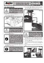
2. Unpack the vertical post (
Fig. 6 ref. 1
) and put it
vertically onto the base.
3. Put the post (
Fig. 6 ref. 1
) onto the base (
Fig. 6
ref. 2
) and fit the pin (
Fig. 6 ref. 3
) into the spe-
cial hole (
Fig. 6 ref. 4
) and block it through the
washers (
Fig. 6 ref. 5
), the spacers (
Fig. 6 ref. 6
)
and the screws (
Fig. 6 ref. 7
). Fix the rod of post
turnover control (
Fig. 6 ref. 8
) cylinder using the
pin (
Fig. 6 ref. 9
) and the seegers (
Fig. 6 ref. 10
).
1
2
7 6
5
3
9 10
6
7
10
8
4
5
Fig. 6
4. At the end mount the rod covering by means of the
supplied screws and washers.
10.3 Bead breaker arm mounting
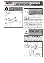
Secure the beading arm vane (
Fig. 7 ref. 1
) using the
washers (
Fig. 7 ref. 2
) and the nut (
Fig. 7 ref. 3
),
on issue (nut and washers are clamped on the bead
breaker vane).
1 2 3
Fig. 7
10.4 Tubeless inflation mounting (only for
versions with tubeless inflation)
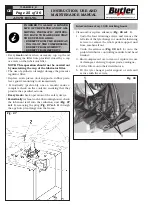
1. Mount the tank (
Fig. 8 ref. 1
) on the base rear part,
as shown in
Fig. 8
, using the screws (
Fig. 8 ref. 2
)
(tightening torque approx. 8 N·m), the washers
(
Fig. 8 ref. 3
) and the nuts (
Fig. 8 ref. 4
).
2
2
1
3
4
3
4
Fig. 8
7300-M023-0_B
HP441S.XX - HP441S.XXFI
HP441SQ.XX - HP441SQ.XXFI


