INSTRUCTION, USE AND
MAINTENANCE MANUAL
Page 20 of 36
GB
12.6.2 Setting the tool for tyre fitting and
removal
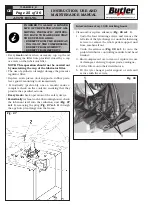
When finished with clamp adjustment, set head po-
sition along its three orthogonal axes using the 14”
diameter sample rim. Tighten the dowels and the
lower screw firmly to lock the head in position. When
finished,
correct head working position
(equipped
with roller or insert)
when locked
should be as shown
in
Fig. 20A-20B
. Tighten bolts and nuts to the follow-
ing torque values:
• lower screw: 70 Nm.
• adjusting clamp bolts: 40 Nm.
mm 3 - 3,5
mm
2
+
0,
5
mm
2
+
1
Car rim
Fig. 20A
mm 12 + 0,5
mm
3
+
0,
5
mm
2
+
1
Rims with projecting spokes
Fig. 20B
7300-M023-0_B
HP441S.XX - HP441S.XXFI
HP441SQ.XX - HP441SQ.XXFI


