Page 32 of 106
INSTRUCTION, USE AND
MAINTENANCE MANUAL
GB
KENDO.30LIGHT-KENDO.30LIGHTFI
7105-M002-0_B
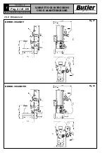
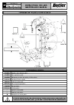
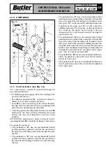
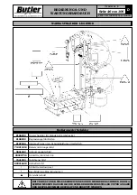
11.1 Control device (see Fig. 14)
The control device consists of a panel with integrated
key and push buttons.
•
The inflation pressure gauge “
A
” for the reading of the
pressure into the tyre.
•
The inflation pushbutton “
B
” , if pushed it allows to
deflate the tyre at the required pressure.
•
Lever
M
for the tools setting on the wheel diameter
through a thrust and return movement pushing in the
same time the unlocking push button
L
.
•
Unlocking push button
L
pushed before the lever
M
starting for the arms placing. Releasing the push
button, the arms lock themselves into the setted
position.
ATTENTION: pushing the push button
L
before
operating the lever
M
to avoid the locking of movements.
The panel
C
consists of:
•
The pushbutton “
D
” has one mechanically holded
position and once pushed it controls the operation of
the upper bead breaking roll cam for its insertion into
the rim.
•
The pushbutton “
E
” has one mechanically holded
position and once pushed it controls the operation of
the lower bead breaking roll cam for its insertion into
the rim.
11.0 CONTROLS
•
The pushbuttons “
F
” have one mechanically holded
position and once pushed they control the vertical shift-
ing of the upper bead breaking roll. If pushed on its
lower part (F2), it will control the shifting downwards,
if pushed on its upper part (F1), it will control the
shifting upwards. The pressure of the push button
(F1) controls the upper bead breaker roll cam
disinsertion if it is previously inserted through the
push button (D).
•
The pushbuttons “
G
” have one mechanically holded
position and once pushed they control the vertical shift-
ing of the lower bead breaking roll. If pushed on its
lower part (G2),it will control the shifting downwards.
The push button pressure (G2) controls the lower bead
breaker roll cam disinsertion if it is previuosly inserted
through the push button (E). If pushed on its upper
part (G1), it controls upward shift.
•
The pushbutton “
H
” has one mechanically holded po-
sition. If pushed it controls the tool vertical transla-
tion in its lower part.
•
The pushbutton “
I
” has one mechanically holded posi-
tion. If pushed it controls the tool vertical translation
in its upper part.
Fig. 14

