Page 33 of 106
INSTRUCTION, USE AND
MAINTENANCE MANUAL
GB
KENDO.30LIGHT-KENDO.30LIGHTFI
7105-M002-0_B
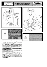
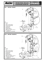
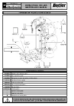
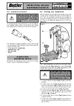
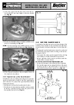
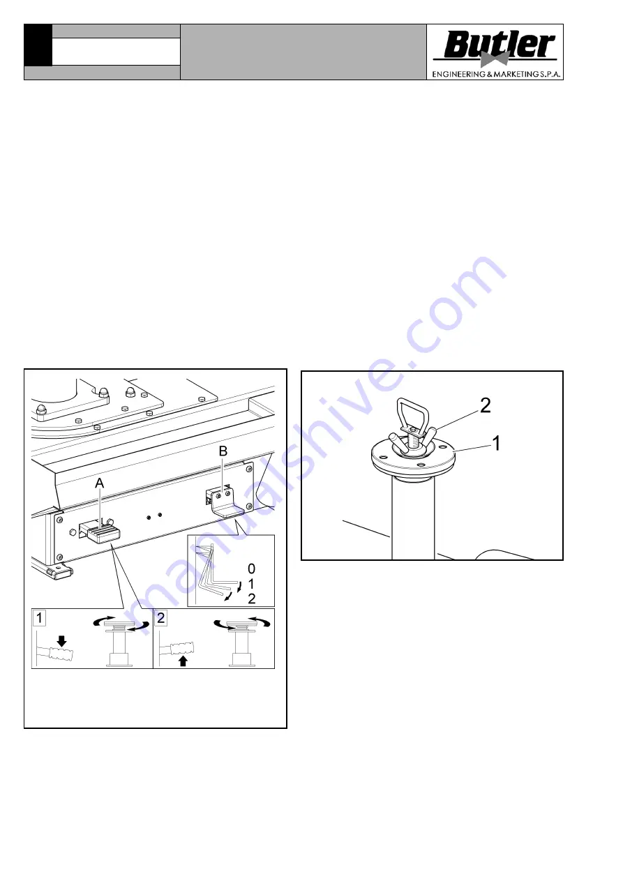
Fig. 15
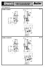
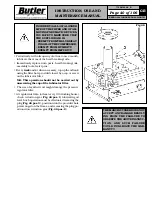
Fig. 16
KEY (pedal
Pos. B
)
Pos. 1 - Tyre inflation with pressure gauge
Pos. 2 - Tyre inflation with pressure gauge +
inflation nozzle
NOTE:
in case of use of rims without central hole, it’s
necessary to use the proper accessory (available
on demand).
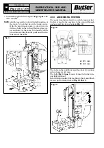
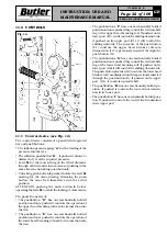
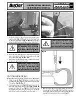
11.2 Pedalboard (see Fig. 15)
The
“pedal A”
has two mechanically holded operative
positions. Pressing it downward the chuck motor ro-
tates in clockwise sense. Lifting the pedal causes a move-
ment in the opposite sense.
NOTE:
Chuck unit speed can be metered continuously
only in clockwise sense: the maximum speed is
reached through a progressive speed on the
pedal.
The
“pedal B”
has a different function depending on the
version on the machine.
Version with inflation with pressure gauge
The inflation pedal in this version has only one func-
tion. A continuous pressure supplies air at a controlled
pressure (max. 4 ± 0,2 bar 58 PSI).
Version with tubeless inflation
The inflation pedal has two functions. The supply of air
at a controlled pressure as in the previous version, and
a second function of a jet of air from the inflation nozzle
to assist the beading in of the tyre.
12.0 USING THE MACHINE
12.1 Preliminary operations - Preparing
the wheel
• Remove the wheel balancing weights from both sides
of the wheel.
• Remove the valve stem and allow the tyre to completely
deflate.
• Establish from which side the tyre should be
demounted, checking the position of the channel.
• Find the rim locking type.
• Try to establish the special types of wheels, such as
“EH2” and “EH2+”, in order to improve locking, bead
breaking, assembly and disassembly performances.
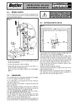
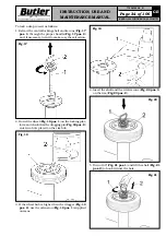
12.2 Wheel locking
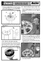
All rims must be locked on the rubber plate (
Fig. 16
pos. 1
) through the central hole using the proper lock-
ing device (
Fig. 16 pos. 2
).

