Page 37 of 106
INSTRUCTION, USE AND
MAINTENANCE MANUAL
GB
KENDO.30LIGHT-KENDO.30LIGHTFI
7105-M002-0_B
1
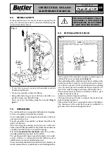
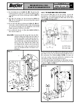
Fig. 34
Fig. 33
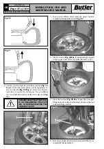
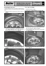
4. Lift the tool through the provided control (
Fig. 14
Pos. I
). When the tool reaches a vertical position re-
lated to the rim (
Fig. 32 Pos. 1
), rotate the chuck so
that the tyre enters the rim groove. Keep on lifting
the tool until the bead is on the rim edge (see
Fig.
31
).
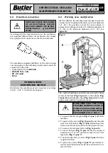
Fig. 32
1
Fig. 31
Fig. 30
Fig. 35
1
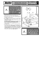
TO MAKE SURE THAT THE TOOL
IS ON DISASSEMBLY POSITION
(FIG. 31) BEFORE STARTING THE
CHUCK ROTATION.
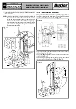
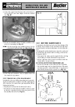
6. Lift the tool (see
Fig. 34
Pos. 1
) maintening it coupled
to the upper bead of the tyre with the lower roller.
7. Place the tool (see
Fig. 35
Pos. 1
) near the rim edge.
Using the lower roller, load the lower bead on the tool
in demounting position.
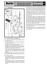
5. Rotate in clockwise sense until the upper bead is
completely disassembled (see
Fig. 33
).
8. Rotate the chuck in clockwise sense until the tyre is
completely disassembled.

