background image

Page 20 of 61

INSTRUCTION, USE AND  

MAINTENANCE MANUAL

EN

W H E N   T H E   E Q U I P M E N T   I S 

TURNED OFF LOSES ALL THE 

M E A S U R E M E N T S   A N D   T H E 

STORED DATA (SIZE, SPINS, US-

ERS, ETC ...). AT RESTARTING, 

PRESSING THE BUTTON 

 (IN 

THE CASE HAVE NOT YET BEEN 

STORED ON THE NEW MEASURES 

AFTER THE SWITCHING ON), THE 

MACHINE DOES NOT PERFORM 

ANY OPERATION.

13.2  Balancing programs setting

The  setting  of  the  balancing  programs  can  be  per-
formed in two ways:
-  through the gauge arm (rapid setting);
-  through “Measurement being acquired” screen, ap-

pearing when the 

 button is pressed (

Fig. 19 

ref. 1

).

The  setting  modes  are  completely  different  even  if 
they allow to reach the same result (but with different 
times).

At  the  bottom  of  the  main  screen  page  and  of  each 
screen page described below, there will be coloured 
rectangles  (

Fig. 19 ref. B

)  located  above  function 

identification icons (

Fig. 19 ref. C

). These functions 

are activated by pressing the appropriate coloured but-
ton on the push-button panel (

Fig. 18 ref. 9

). Press 

the button (

Fig. 19 ref. 3

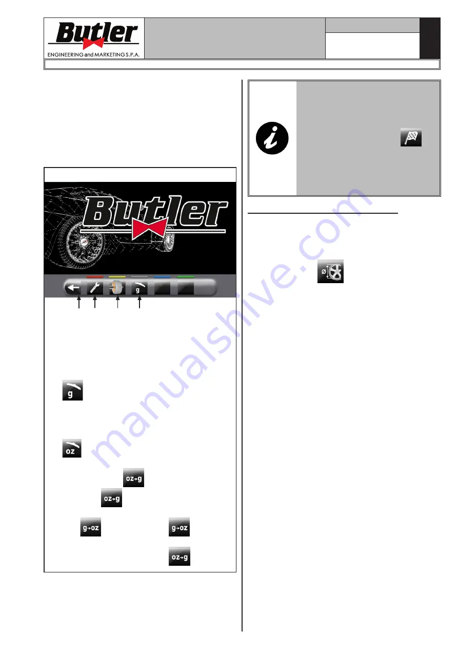
) to display a second page 

where you can access the "Technical assistance" menu 
and the "Run-out" menu (see 

Fig. 20

).

Fig. 20

1

2

3

4

KEY
1 – User menu
2 – Run-out menu (visible only if active)
3 – Return to previous page
4 – Measurement unit setting.

The machine is supplied with “grams” option 

 enabled (see Chap. 14.0), so weights will 

be displayed only in grams and no icons will 
be displayed onto push button 4.
In order to modify the measurement unit carry 
out the following procedure: if “ounce” option 

 is activated from user menu (see Chap. 

14.0), “ounce” weight displaying mode is set, 

and push button 

 will be displayed. Press 

the button 

 to set machine weight display 

in grams and on the screen will be displayed 

icon 

. Press the button 

 to set ma-

chine  weight  display  in  ounces  and  on  the 

screen will be displayed icon 

.

In order to turn off the machine, simply press the “OFF” 
main switch (

Fig. 13 ref. 1

).

1296-M024-01

LIBRAK350 - LIBRAK350PRO

Summary of Contents for LIBRAK350

Page 1: ...rts drawings refer to LIST OF COMPONENTS section TRANSLATION FROM THE ORIGINAL INSTRUCTIONS BUTLER ENGINEERING and MARKETING S p A a s u Via dell Ecologia 6 42047 Rolo RE Italy Phone 39 0522 647911 Fax 39 0522 649760 e mail Info butler it 1296 M024 01 LIBRAK350 LIBRAK350PRO 1296 M024 01 Rev n 01 09 2021 ...

Page 2: ...ght___________24 13 3 1 Weights positioning_________________25 13 4 Displaying the active modifiable field__25 13 5 Wheel balancing screen page description_____________________________26 13 5 1 Balancing mode_____________________28 13 6 Use of machines with disabled automatic data gauge__________________30 13 6 1 Manual setting of wheel dimensions_________________________31 13 7 Standard balancing...

Page 3: ...1 Technical electrical data_______________58 17 2 Technical mechanical data_____________58 17 3 Dimensions_____________________________59 18 0 STORING____________________________ 60 19 0 SCRAPPING_________________________ 60 20 0 REGISTRATION PLATE DATA_______ 60 21 0 FUNCTIONAL DIAGRAMS___________ 60 Drawing A Electrical connection diagram__61 LIBRAK350 LIBRAK350PRO 1296 M024 01 ...

Page 4: ...f 61 INSTRUCTION USE AND MAINTENANCE MANUAL Model Feature Fixtures Versions LIBRAK350 LIBRAK350PRO External data gauge OPT 1 off road vehicle cone D 88 132 standard OPT optional LIBRAK350 LIBRAK350PRO 1296 M024 01 ...

Page 5: ...aded chuck 5 Protection guard 6 Pedal brake 7 Main switch 8 Grippers for weight fitting 9 Rapid ring nut 10 Pressure ring 11 Grippers for weights 12 Carriages counterweight 13 Cones protection cup 14 Manual caliper 15 External data gauge standard on some models 16 Off road vehicle cone D 88 132 standard on some models LIBRAK350 LIBRAK350PRO 1296 M024 01 ...

Page 6: ...ty goggles Warning Be particularly careful possible material damages Mandatory Operations or jobs to be performed compulsorily Symbols Description Danger Be particularly careful Move with fork lift truck or pal let truck Lift from above Note Indication and or useful information Attention never lift the machine by means of the chuck LIBRAK350 LIBRAK350PRO 1296 M024 01 ...

Page 7: ...on device use plate 999912940 Lifting plate 999914160 230V 50 60 Hz 1 Ph voltage plate 999915200 Serial number plate 999916311 Rubbish skip plate 999917640 Manufacturer plate 999924470 Machine nameplate QR code plate IF ONE OR MORE PLATES DISAPPEAR FROM THE MACHINE OR BECOMES DIFFICULT TO READ REPLACE IT AND QUOTE ITS THEIR CODE NUMBER S WHEN REORDERING LIBRAK350 LIBRAK350PRO 1296 M024 01 ...

Page 8: ...d rapid operation With just a small degree of maintenance and care this wheel balancer will give you many years of trouble free service and lots of satisfaction 2 0 INTENDED USE The machine described in this manual and their different versions is a wheel balancing machine for car and light transport projected to be used exclusively to cancel out or at least reduce to ac ceptable limits the vibrati...

Page 9: ...ty devices or with the warning signals placed on the machine leads to serious dangers and represents a transgression of European safety standards Use of the machine is only permitted in places free from explosion or fire hazard and in dry places under cover Original spare parts and accessories should be used THE MANUFACTURER DENIES ANY RESPONSIBILITY IN CASE OF DAMAGES CAUSED BY UNAU THORIZED MODI...

Page 10: ...TS DANGLING OBJECTS LIKE BRACELETS MUST NOT BE WORN AND LONG HAIR MUST BE TIED UP FOOTWEAR SHOULD BE ADEQUATE FOR THE TYPE OF OPERATIONS TO BE CAR RIED OUT The machine handles and operating grips must be kept clean and free from oil The workshop must be kept clean and dry Make sure that the working premises are properly lit The machine can be operated by a single operator Unauthorized personnel mu...

Page 11: ...INJURY CAUSED BY CONTACT WITH PACKAGING MATERIAL NAILS ETC The cardboard box is supported with plastic strapping Cut the strapping with suitable scissors Use a small knife to cut along the lateral axis of the box and open it like a fan It is also possible to unnail the cardboard box from the pallet it is fixed to After removing the packing and in the case of the machine packed fully assembled chec...

Page 12: ... 15 4 psi The use of the machine in ambient conditions other than those specified above is only allowed after prior agreement with and approval of the manufacturer 8 1 Working area Fig 3 USE THE MACHINE IN A DRY AND SUFFI CIENTLY ILLUMINATED PLACE CLOSED PRO TECTED FROM ALL WEATHER CONDITIONS AND COMPLYING WITH THE REGULATIONS IN FORCE REGARDING WORK SAFETY The location of the machine requires a u...

Page 13: ...are laid down flat and correctly in contact with the fix ing surface itself If not so insert shimming profiles between the machine and the fixing lower surface as indicated in Fig 4 IT IS MANDATORY TO SECURE IF WHEELS WEIGHING MORE THAN 30 KG 66 LBS ARE USED a 270 mm 10 63 b 480 mm 18 90 Fig 4 To fasten the product to the ground use anchoring plugs Fig _4 ref 1 with a threaded shank M8 UNC 5 16 su...

Page 14: ... the plate Fig 6 ref 5 using bolts Fig 6 ref 6 washers Fig 7 ref 7 and nuts Fig 6 ref 8 3 Secure the plate complete with microswitch Fig 6 ref 3 using bolts Fig 6 ref 9 washers Fig 6 ref 10 and nuts Fig 6 ref 11 PAY ATTENTION MICROSWITCH LEVER FIG 6 REF 4 MUST BE ADJUSTED BY SCREWDRIVER 4 Mount the protection guard Fig 6 ref 12 to the support Fig 6 ref 3 interposing the washers Fig 6 ref 13 and 14...

Page 15: ...the support pipe Fig 7 ref 4 fit the monitor support Fig 7 ref 7 and lock it through the nut Fig 7 ref 8 Then screw the previously removed nuts and washers again Fig 7 2 Connect the plugs on the power supply sockets and monitor signal Connect the wiring of the keyboard 3 Secure the monitor Fig 8 ref 1 to the support Fig 8 ref 2 with the bolts Fig 8 ref 3 and the washers Fig 8 ref 4 supplied Fig 8 ...

Page 16: ...sly removed washers Fig 10 ref 11 Secure bracket Fig 10 ref 4 to the support guard Fig 10 ref 14 with the bolts Fig 10 ref 8 and the washers Fig 10 ref 9 Lock the gauge arm Fig 10 ref 3 to the brackets Fig 10 ref 2 4 using the 2 bolts Fig 10 ref 5 the washers Fig 10 ref 6 and the nuts Fig 10 ref 7 so that the shaft and the gauge arm are lev elled see Fig 11 Fig 10 5 Also make sure the gauge tip Fi...

Page 17: ... with local and applicable regu lations This operation must be performed by expert and professional personnel FIT A TYPE APPROVED AS RE PORTED BEFORE PLUG TO THE MACHINE CABLE THE GROUND WIRE IS YELLOW GREEN AND MUST NEVER BE CONNECTED TO ONE OF THE TWO PHASE LEADS MAKE SURE THAT THE ELECTRI CAL SYSTEM IS COMPATIBLE WITH THE RATED POWER AB SORPTION SPECIFIED IN THIS MANUAL AND APT TO ENSURE THAT V...

Page 18: ...t suit able for the wheel to be balanced These accessories must be selected according to the shape of the rim Carefully position the wheel Fig 14 ref 3 fit ting the cone Fig 14 ref 2 on the shaft Fig 14 ref 1 otherwise this could seize until this rests against the support flange Fig 14 ref 4 3 Fit the wheel with the inner side of the rim towards the wheel balancer and against the cone Fig 14 4 Fit...

Page 19: ...on red 3 Function push button yellow 4 Function push button grey 5 Function push button blue 6 Function push button green 7 Previous page push button 8 Next page print push button 9 Push button panel keyboard with 7 keys LIBRAK350 LIBRAK350PRO 1296 M024 01 13 0 WHEEL BALANCING 13 1 Switching the machine on and off Press the ON switch Fig 13 ref 1 located in the rear part of the equipment Wait a fe...

Page 20: ...hese functions are activated by pressing the appropriate coloured but ton on the push button panel Fig 18 ref 9 Press the button Fig 19 ref 3 to display a second page where you can access the Technical assistance menu and the Run out menu see Fig 20 Fig 20 1 2 3 4 KEY 1 User menu 2 Run out menu visible only if active 3 Return to previous page 4 Measurement unit setting The machine is supplied with...

Page 21: ...ntact the weights fitting gripper with the inner part of the rim 2 contact points see Fig Fig 21 to select ALU S program REPEATEDLY BRINGING THE CALIPER ARM FIG 22 REF 1 IN CONTACT WITH THE CHUCK FIG 22 REF 2 THE PROGRAM WILL CYCLE FROM ALU S TO ALU S1 TO ALU S2 RETURN ING THEN AT THE BEGINNING WHENEVER THE DISTANCE DI AMETER CALIPER AND OR THE EXTERNAL DATA GAUGE SEE FIG 23 IF ANY IS KEPT IN PO S...

Page 22: ...to spin at low speed 30 rpm and at the end of the measure ment the eccentricity graph appears as shown in the Fig _28 1296 M024 01 LIBRAK350 LIBRAK350PRO Measuring procedure of electronic RUN OUT with the distance diameter caliper arm The electronic RUN OUT measuring device is useful to check if the rim has some imperfections To access the screen to choose the rim control mode proceed as follows f...

Page 23: ...ref 3 indicates the position of the rim in 12 o clock position 13 2 2Programs setting through Measure ments acquisition screen page From the Home page press the Fig 19 ref 1 button to display Measurements acquisition screen page below PRESS THE BUTTON Fig 19 ref 1 TO DISABLE THE AUTO MATIC FUNCTIONS FOR THE SELECTION OF THE BALANC ING PROGRAM OF DISTANCE DIAMETER CALIPER ARM DESCRIBED IN PAR 13 2 ...

Page 24: ...d measures you can spin the wheel by pressing the button and closing the protective guard 13 3 Indicative display of points where to detect measures to fit weight IT IS VERY IMPORTANT TO RE MEMBER THE POINTS SELECTED FOR MEASUREMENT INSIDE THE RIM SINCE DURING THE WEIGHTS FITTING WITH FIXED LASER YOU WILL NOT HAVE ANY OTHER REFERENCE EXCEPT FOR THE CROSS LINE ON THE RIM GEN ERATED BY THE LASER ITS...

Page 25: ... programs IF ALL MEASURES REQUIRED BY THE PROGRAM HAVE NOT BEEN TAKEN INSERTED THE MACHINE DOES NOT ALLOW THE WHEEL SPIN TO DETECT THE UNBAL ANCE 13 4 Displaying the active modifiable field During the various phases of measures detection the active field turns yellow Pressing the buttons or you can change the value and or program inside the active field To change the selected active field simply p...

Page 26: ... 3 1 a b 5 c 4 d 10 KEY 1 Measures used by the program to perform the spin and detect the values in P1 P2 P1 Weight to be fitted on rim outer side P2 Weight to be fitted on rim inner side 2 Wheel placed to fit the weight on wheel outer side arrows both green 3 Wheel not placed to fit the weight on wheel inner side blue black arrows 4 Wheel balancing suggestions 4a SPLIT Program Clip weights progra...

Page 27: ... Par 14 1 Op tions menu On the following screen page press the button to display the weight with maximum resolution 1g to be fitted on the wheel expressed in grams The following screen will appear on the moni tor Press again the button to display the approximated weight to be fitted to the wheel expressed in grams 7b Display of the weights in OUNCES GRAMS Set the unit of measurement for weights di...

Page 28: ...n will appear on the monitor 13 5 1Balancing mode The machine has the ability to perform the wheel bal ancing weights fitting in 4 different ways using the distance diameter caliper arm with weights fitting grippers weights fitting at 6 o clock without the use of laser emitter Weights fitting with distance diameter caliper arm 1 Place the adhesive weight on the arm grippers Fit the adhesive weight...

Page 29: ...MENU OPTIONS DESCRIBED IN PAR 14 1 TO USE THIS WEIGHT APPLICA TION MODE THE OPERATOR MUST REMEMBER THE PRECISE POINT WHERE THE MEASURE MENT WAS TAKEN WITH THE DISTANCE DIAMETER CALIPER ARM USING THIS MODE THE MA CHINE ALLOWS YOU TO APPLY ANY ADHESIVE WEIGHTS THAT WOULD BE APPLIED WITH DIS TANCE DIAMETER CALIPER AT 6 O CLOCK IF AFTER YOU EN ABLE THIS MODE ON BALANCING PROGRAM APPEARED AGAIN THE ICO...

Page 30: ...llowing figure on the left column of the table locate the detected value and identify the corresponding value to enter type the value to be entered in the appropriate field on the display VALUE DETECTED ON THE GRADUATED SCALE VALUE IN MILLIMETRES TO BE ENTERED VALUE IN INCHES TO BE ENTERED 0 5 5 0 20 1 10 0 40 1 5 15 0 60 2 20 0 80 2 5 25 1 00 3 30 1 20 3 5 35 1 40 4 40 1 60 4 5 45 1 80 5 50 1 95 ...

Page 31: ...s in mm where you must remove the gauge arm Fig 32 ref _1 2 to apply the weights inside the rim 13 7 Standard balancing programs 13 7 1Static The STATIC program permits balancing wheels by fit ting adhesive weights on the outer and inner sides of the rim Enter the measurements see Par 13 2 1 or 13 6 1 and proceed as described in Par 13 5 At the end of the procedure the wheel balancing condi tions ...

Page 32: ...cing condi tions can be checked by performing a trial spin The procedure has now been completed 13 7 5ALU S ALU S program permits balancing wheels by two fit ting adhesive weights on the outer and inner sides of the rim Enter the measurements see Par 13 2 1 or 13 6 1 and proceed as described in Par 13 5 At the end of the procedure the wheel balancing condi tions can be checked by performing a tria...

Page 33: ...i tions can be checked by performing a trial spin The procedure has now been completed 13 7 9ALU 2 ALU 2 function balances wheels with light alloy rims by fitting adhesive weights on the outside and inside of the rim The position of the outer weight is not visible but hidden inside Enter the measurements see Par 13 2 1 or 13 6 1 At the end of the procedure the wheel balancing condi tions can be ch...

Page 34: ...ocedure represents a modern system for the reset of the unbalance in order to reduce weights con sumption This procedure ensures a fastest execution of the operations thanks to a lesser number of spins and repositioning After making the wheel spin in ALU S mode the moni tor shows the total of 2 adhesive weights to precisely correct STATIC and DYNAMIC unbalance It is possible to fit a single weight...

Page 35: ... procedure 5 Residual dynamic unbalance value if the value is yellow it is not recommended to carry out ECO WEIGHT procedure 6 Arrows indicating the weight fitting point with distance diameter caliper arm Press the brake pedal and fit the adhesive weight inside pliers as shown in Fig 34 Fig 34 Fit the adhesive weight in the pliers of the gauge rod Pull out the gauge rod until the arrows Fig 33 ref...

Page 36: ...ES ARE YELLOW THE PROGRAM SUGGESTS USING THE STANDARD ALU S PROCEDURE 13 8 2SPLIT mode Split procedure proves useful when the dynamic unbal ance of a wheel is fairly high and the weight to be fitted is not available for instance a 100 g weight It s possible then to correct the unbalance dividing the amount of weight into two weights of smaller size Split procedure eliminates errors by using DYNAMI...

Page 37: ...screen will be displayed where you must enter the value of the weights to be fitted Press button to select the outer weight to edit Press buttons or to increase or decrease the total weight to be fitted THE YELLOW VALUE INDICATES WHICH VALUE IS ACTIVE AND YOU ARE EDITING THE HIGHER THE CHOSEN WEIGHTS VALUE IS THE MORE THEY WILL BE SPACED After choosing the value of the weights to be fitted press b...

Page 38: ...pplied the weights correctly 13 8 3Weights hidden behind spokes mode Adhesive correction weight positioning may not look attractive on some types of rims In this case weights hidden behind spokes mode can be used it splits any correction weight on the outer side into two parts to be hidden behind rim spokes It can be used in ALU S mode Proceed to ALU S unbalance measurement displaying by performin...

Page 39: ...position shown by the machine as explained in Par 13 5 1 Press the button to confirm that they have applied the FIRST weight and to automati cally position the wheel for the fitting of the 2nd weight The monitor shows the amount of weight to be applied behind the SECOND spoke Pull out the gauge rod and fit the SECOND weight in the position shown by the machine as done for the first weight Press th...

Page 40: ...he unbalance values verify that the machine displays the ability to use the matching op tions Fig 30 ref 4a Press button to shift to the next screen page Press button to enter the relevant function On the monitor the next screen page will be displayed STEP 1 Move the slider on the flange to the 12 o clock position Make a reference mark using chalk for in stance on the rim and tyre in line with the...

Page 41: ... back in position close the protection guard to make an automatic wheel spin At the end of the spin the monitor will display the screen illustrated afterwards 1 2 3 Fig 36 In this screen you will see the dynamic unbalance that the wheel had before performing the operation Fig 36 ref 1 the dynamic unbalance after having rotated the tyre through 180 compared to the rim Fig 36 ref 2 and the unbalance...

Page 42: ...s on different planes are used on rim inner side To launch a PAX measurement proceed as follows Make sure there are no stones and or mud on the wheel Remove any counterweights Fit the wheel and make sure it is properly fastened see Chap 11 Press button from Home page On the screen that appears press the button to switch to measuring mode selection screen below Use the arrows or to select PAX mode ...

Page 43: ... fields that are consistent with those measures that were taken previously and at the same time erases all measures which are not consistent 13 11 Wheel balancing in Motorcycle mode with distance caliper extension Kit By enabling motorcycle wheel balancing function the wheel balancers can also balance motorcycle wheels Before detecting the wheel sizes see Par 13 2 2 se lect motorcycle wheel balanc...

Page 44: ...s menu push button 14 1 Options menu Press button to display the monitor screen to enable disable the options as shown below Press button several times to display the second option screen page reported as follows To enable disable individual functions simply high light the icon using the buttons and or and press the button Pressing the button may involve besides the change in the unit of measure f...

Page 45: ...isable ECO WEIGHT function Enable disable the positioning of adhe sive weights at 6 o clock Enable disable the lock function for caliper arm in position It allows you to change the unit of measure of the distance of the weights fitting point from mm to inches and vice versa Enable disable the LED light Enable disable the dynamic residues in the ECO WEIGHT function Enable disable the functions of m...

Page 46: ...is limit can be set from 10 g to 1 g from 0 5 oz to 0 05 oz At the end of the spin however by pressing the button the weight can be displayed with maximum resolution of 1 g 0 05 oz not considering the set lower limit LOWER LIMIT FACTORY SETTING FOR DYNAMIC WHEEL BALANC ING MODE IS 5 g 0 25 oz THE LOWER LIMIT FOR ALL THE OTH ER MODES IS SET AT 7 g 0 35 oz 1 2 3 4 Default values Work range g oz g oz...

Page 47: ...wing screen 1 2 KEY 1 Weights thickness height default value 4 mm 0 16 2 Weights width default value 19 mm 0 75 From this screen page change the size values of weights using the buttons and THE YELLOW COLOURED VALUE IS THE ACTIVE FIELD AND THE MODIFIABLE ONE 14 1 3User management The User Management function is disabled on ma chine delivery To enable it proceed as described in Para 14 1 After enab...

Page 48: ...You can recall the desired user each time the pro gram displays the specific button Fig 41 ref 2 and Fig 42 ref 1 The measurements stored for each user are lost when the machine is switched off User management is valid for any wheel balancer function TO ENABLE OR DISABLE USER MANAGEMENT FUNCTION SEE PARAGRAPH 14 1 IF THE FUNC TION IS DEACTIVATED BUTTON IS DISPLAYED 14 2 Enabling of electronic Run ...

Page 49: ...dividual functions simply high light the icon using the buttons and or and press the button Remove symbol X on the icon Fig 43 ref 1 After you select deselect the desired options exit the menu by pressing push button 14 3 Machine calibrations Press the button Fig 39 ref 2 to display the following screen page on monitor Fig 44 1 2 3 KEY 1 Chuck 0 zero calibration 2 Weight measurement sensors calibr...

Page 50: ... VALUES SHOWN IN THE FIGURES BELOW ARE PURELY ILLUSTRATIVE ASSEMBLE A BALANCED WHEEL ON THE SPINDLE AND PERFORM THE CHUCK 0 ZERO CALIBRA TION PROCEDURE DESCRIBED IN PAR 14 3 1 WITH WHEEL MOUNTED Press the button Fig 44 ref 2 to display the following screen page on the monitor Set the size of the rim on the chuck using the dis tance diameter caliper arm Set the rim width using one of the following ...

Page 51: ...de at 12 o clock Press the brake pedal and hold it down during the whole the following operation to avoid unexpected rotation of the chuck Remove the weight from 100 g 3 52 oz from the outside of the wheel and apply it on the inner side at 12 o clock AT THIS POINT TAKE THE WEIGHT POSITIONED ON THE EXTERNAL SIDE AND PLACE IT EXACTLY IN THE SAME POSITION BUT ON THE INTERNAL SIDE HELPING BY DRAWING A...

Page 52: ...STRATIVE Press the button to display the following screen page on the monitor Place the gauge Fig 45 ref 1 on the chuck flange Fig 45 ref 2 Fig 45 2 1 The following screen will appear on the monitor to indicate the measured values 2 1 Fig _46 KEY 1 Example of value detected by the gauge 2 Example of value on threaded chuck The value next to the symbol scale Fig _46 ref 1 must be equal to or 1 mm 0...

Page 53: ...huck in the lower part of the it but on a smaller diameter than before as indicated on the image on the monitor Press push button On the monitor the next screen page will be dis played Measure the exact diameter of a rim see Fig 47 and place it on the screen on the monitor by pressing the or buttons Fig 47 Fit the measured wheel on the balancer and lock it on the chuck LIBRAK350 LIBRAK350PRO 1296 ...

Page 54: ...shed Calibration of external data gauge standard on some models THE NUMERICAL VALUES SHOWN IN THE FIGURES BELOW ARE PURELY ILLUSTRATIVE Press the button to display the following screen page on the monitor TO PERFORM THIS CALIBRATION THE CHUCK MUST BE UNLOADED NO WHEEL OR ACCESSORIES MOUNTED ON IT Move the tip of the width measuring device Fig 49 ref 1 by the chuck end Fig 49 ref 2 in case of pneum...

Page 55: ...e displayed Move the tip of the width measuring device Fig 50 ref 1 in line with the outer surface of the flange Fig 50 ref 2 Fig 50 Press button At the end of the operation the following screen will appear on the monitor The calibration of the external data gauge is finished LIBRAK350 LIBRAK350PRO 1296 M024 01 ...

Page 56: ...peed not reached 3 Calibration overcoming 4 Wheel speed stability out of tolerance 5 Encoder calibration error 6 Encoder samples not sufficient 7 Chuck calibration error 8 Piezo calibration values out of tolerance 9 Wheel rotations not completed 11 Incorrect gain calibration 14 Firmware error 15 Runout samples not sufficient 28 Piezo calibration error 29 Distance out of tolerance level 31 Distance...

Page 57: ... BLOW IT WITH COMPRESSED AIR Do not use solvents to clean the pressure regulator ANY DAMAGE TO THE MACHINE DEVICES RESULTING FROM THE USE OF LUBRICANTS OTHER THAN THOSE RECOMMENDED IN THIS MANUAL WILL RELEASE THE MANUFACTURER FROM ANY LIABILITY 16 0 ROUTINE MAINTENANCE BEFORE CARRYING OUT ANY ROU TINE MAINTENANCE OR ADJUST MENT PROCEDURE POSITION THE MAIN SWITCH 0 DISCON NECT THE MACHINE FROM THE ...

Page 58: ...ases 1 Frequency Hz 50 60 Typical current draw A 0 3 Rotation speed rev min 100 17 2 Technical mechanical data Balancing precision g 1 0 03 oz Rim width setting inches 1 5 22 Rim diameter setting inches 10 26 automatic 10 30 manual Cycle time sec 6 Sound emission level dBA 70 Max wheel weight kg 65 143 lbs Weight Kg 120 265 lbs LIBRAK350 LIBRAK350PRO 1296 M024 01 ...

Page 59: ...INSTRUCTION USE AND MAINTENANCE MANUAL EN Page 59 of 61 17 3 Dimensions Fig 51 Standard on some models LIBRAK350 LIBRAK350PRO 1296 M024 01 ...

Page 60: ...f the crossed dustbin symbol reported on the equipment indicates that the product must not be thrown among the undifferentiated rub bish that is to say together with the mixed urban waste but it has to be managed separately to let the WEEE go through special operations for their reuse or treatment in order to remove and dispose safely the waste that could be dangerous for the environment and to ex...

Page 61: ...ction 16 Limit switch 17 Power supply cable 18 Monitor card kit 19 Monitor 20 Keyboard cables 21 7 keys keyboard 22 Width potentiometer extension cable 23 Potentiometer with shielded cable 24 Cable from transformer to power supply 129605560 REAR PIEZO FRONT PIEZO ENCODER DISC GUARD DISTANCE CALIPER GUARD MICRO DIAMETER CALIPER 3 4 5 220V 24V 20 21 P1 P3 VGA 18 17 19 24 1 2 220V 50Hz IEC JP17A GND ...

Page 62: ... den nachstehenden anwendbaren Normen entspricht objet de cette déclaration est conforme aux Directives applicables suivantes al que se refiere esta declaración cumple con las siguientes Normas aplicables 2006 42 CE Direttiva Macchine 2014 30 UE Direttiva Compatibilità Elettromagnetica Per la conformità alle suddette direttive sono state seguite le seguenti Norme Armonizzate To comply with the abo...

Reviews: