INSTRUCTION, USE AND
MAINTENANCE MANUAL
GB
Page 24 of 66
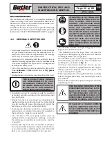
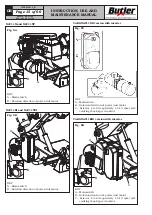
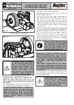
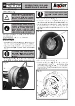
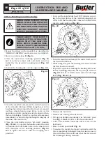
• Lower the mandrel (
Fig.
_
26 ref.
_
C
) until locking
the tool in the extraction position (
Fig.
_
26 ref.
_
D
).
C
D
Fig.
_
26
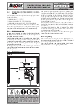
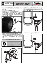
• Translate the tool outwards (
Fig.
_
27 ref.
_
E
) until
the bead is brought to mounting position.
E
Fig.
_
27
• Then rotate the wheel clockwise until the first bead
has completely gone out.
For all versions
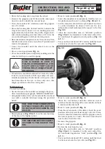
• Once the external bead has been removed, move tool
holder arm away from the wheel, unhook it and lift
it bringing it in “off-work” position (
Fig.
_
15 ref.
_
1
);
use the handle control to position the tool holder arm
on the inner side of the wheel then place it in work
position again (
Fig.
_
14 ref.
_
1
) and secure with the
coupling lever provided.
PAY ATTENTION WHEN REPOSI-
TIONING THE TOOL HOLDER ARM
TO AVOID CRUSHING HANDS.
ALWAYS MAKE SURE THAT THE
ARM IS CORRECTLY HOOKED TO
CARRIAGE.
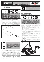
• Move to work position
D
(
Fig.
_
6
).
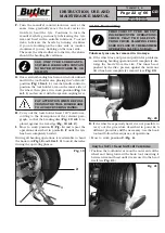
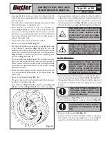
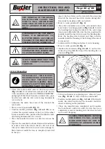
• Carry out the tools holder head 180° rotation in order
to insert the hook tool (
Fig.
_
28 ref.
_
1
) between the
rim edge and the tyre bead.
Fig.
_
28
1
• Move the rim away from the tool by about 4-5 cm
to avoid possible unhooking of the bead from the
same tool.
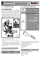
• Move to work position
B
(
Fig.
_
6
).
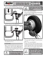
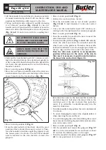
• Translate the hook tool outwards to allow easy inser-
tion of the lever between the rim and the bead on the
tool left. Keeping the lever pressed, lower the wheel
until the edge of the rim is 5 mm distant from the
hook tool then turn the mandrel counterclockwise
until the tyre has been completely removed.
THE REMOVAL OF THE BEADS
FROM THE RIM CAUSES THE
TYRE TO FALL. ALWAYS MAKE
SURE THAT NO ONE IS STAND-
ING BY ACCIDENT IN THE WORK
AREA.
7505-M001-3_B
NAV11N - NAV11NT
NAV11EI - NAV11TEI

