INSTRUCTION, USE AND
MAINTENANCE MANUAL
GB
Page 29 of 66
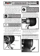
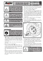
• Lift the mandrel arm with the tyre hooked and turn
it counterclockwise by about 15-20 cm; the tyre will
position itself sideways with respect to the rim.
• Tilt up tool holder arm, unhook it and lift it placing
it in “off-work” position (
Fig.
_
15 ref.
_
1
); use the
handle control to position the tool holder arm on the
inner side of the wheel then place it in work position
(
Fig.
_
14 ref.
_
1
) and secure with the coupling lever
provided.
PAY ATTENTION WHEN REPOSI-
TIONING THE TOOL HOLDER ARM
TO AVOID CRUSHING HANDS.
ALWAYS MAKE SURE THAT THE
ARM IS CORRECTLY HOOKED TO
CARRIAGE.
• Carry out the tools holder head 180° rotation, accord-
ing to the descriptions in the relevant paragraph, in
order to insert the hook between the rim edge and the
tyre bead; the operation must be carried out during
mandrel rotation.
• Move to work position
D
(
Fig.
_
6
).
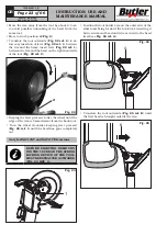
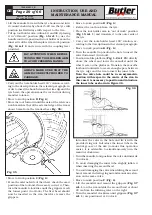
• Move the tool forward until the axis of the reference
notch matches that of the external edge of the rim at
about 5 mm from the rim itself (see
Fig.
_
35
).
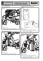
Fig.
_
35
• Move to work position
C
(
Fig.
_
6
).
• From the external side of the wheel, check the exact
position of the tool and, if necessary, correct it. Then,
turn the mandrel clockwise until the grippers reach
the lowest point (6 o’clock). The first bead should
now be inserted in the rim, therefore remove the
grippers.
• Move to work position
D
(
Fig.
_
6
).
• Extract the tool hook from the tyre.
• Place the tool holder arm in “out of work” position
(
Fig.
_
15 ref.
_
1
) and translate it to the outer side of
the tyre.
• Carry out the tools holder head 180° rotation, ac-
cording to the descriptions in the relevant paragraph.
• Move to work position
B
(
Fig.
_
6
).
• Turn the mandrel to position the hole to insert the
valve downward (6 o’clock).
• Position mobile platform (
Fig.
_
1-2 ref.
_
15
) directly
above the wheel and lower the mandrel until the
wheel rests on the platform. Translate the movalbe
footboard outwards to create enough space between
the tyre edge and the rim to insert the inner tube.
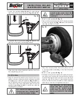
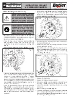
Note: the valve hole could be in an asymmetric
position with respect to the centre of the rim. In
this case it is necessary to position and introduce
the inner tube as shown in Figure 36.
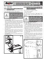
Fig.
_
36
Introduce the valve in the hole and fix it with the
provided ring nut. Introduce the inner tube in the
central groove of the rim (to make this operation
easier, it is advisable to simultaneously turn the
mandrel clockwise).
• Turn the mandrel and position the valve downwards
(6 o’clock).
• To avoid damaging the inner tube, slightly inflate it
when inserting the second bead.
• To avoid damaging the valve when fitting the second
bead, remove the fixing ring nut and mount an exten-
sion on the same valve.
• Move to work position
C
(
Fig.
_
6
).
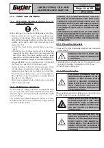
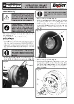
• Lift the mandrel and mount the grippers (
Fig.
_
37
ref.
_
1
) on the rim outside the second bead at about
20 cm from the inflating valve on the right.
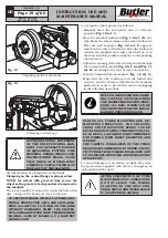
• Turn the mandrel clockwise until grippers (
Fig.
_
37
ref.
_
1
) are positioned at 9 o’clock.
NAV11N - NAV11NT
NAV11EI - NAV11TEI
7505-M001-3_B

