INSTRUCTION, USE AND
MAINTENANCE MANUAL
GB
Page 3 of 66
NAV11N - NAV11NT
NAV11EI - NAV11TEI
7505-M001-3_B
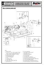
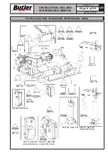
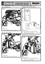
FIG. 1 - NAV11N - NAV11NT
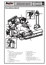
KEY
1 - Main switch
2 - Selector 1-0-2 self-centring chuck
speed control (version with inverter)
3 - Tools carriage translation cylinder
4 - Hydraulic power unit
5 - Self-centring chuck
6 - Bead breaking disc
7 - Tool
8 - Coupling lever
9 - Tool holder arm
10 - Tools unit (only for NAV11N)
11 - Quick fit tool
12 - Tools carriage
13 - Mandrel rotation motor
14 - Mandrel arm
15 - Movable footboard
16 - Electric panel
17 - Control unit
18 - Mandrel arm cylinder
19 - Tools unit (only for NAV11NT)
20 - Bead breaking roll (only for NAV11N)
21 - Tools unit lifting handle
22 - Control unit (version with inverter)
23 - Electrical panel (version with inverter)


