INSTRUCTION, USE AND
MAINTENANCE MANUAL
GB
Page 9 of 66
3.0 SAFETY DEVICES
PERIODICALLY, AT LEAST MONTHLY, CHECK THE INTEGRITY AND THE FUNCTIONAL-
ITY OF THE SAFETY AND PROTECTION DEVICES ON THE MACHINE.
All the machines are equipped with:
• “man-operated” controls (immediate stop of operation when the control is released).
• Controls logic disposition
To prevent the operator from making dangerous mistakes.
• Thermal magnetic switch on the supply line of the oil-pressure power unit motor: avoids the motor overheat-
ing in case of intensive use.
NO MODIFICATION OR CALIBRATION OF THE OPERATING PRESSURE OF THE MAXI-
MUM PRESSURE VALVE OR OF THE HYDRAULIC CIRCUIT PRESSURE LIMITER IS
PERMITTED
• Maximum pressure valve on oil-pressure pump delivery, in order to protect the whole line from overpressures
caused by accidental overloads;
• controlled check valves on:
- opening of clamping unit jaws,
Such valves are installed to avoid that accidental oil leakages provoke unwelcome jaws movements (and as
a consequence the fall of the wheel).
• Fuses on the electric supply line of the clamping unit motor,
• Automatic power supply disconnection with the opening of the electric panel.
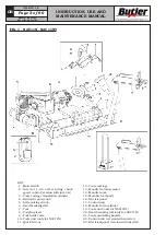
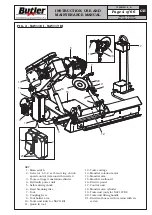
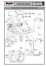
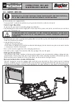
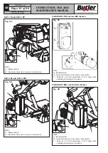
• Fixed guards and shelters
The machine is fitted with a number of fixed guards intended to prevent potential crushing, cutting and com-
pression risks. These protections have been realized after risks evaluation and after all machine operative
situations have been considered. These protections can be located in the figure below.
• Motor protection devices (version with inverter)
The new “Invemotor” motor is equipped with electronic protection devices. They stop the motor if working
defected conditions appear to avoid that the motor itself can be damaged and that the operator safety can be
compromised (overvoltage, overload, overtemperature). For other details, see the chapt. 14 “Fault-Finding”.
Fig.
_
3
NAV11N - NAV11NT
NAV11EI - NAV11TEI
7505-M001-3_B


