INSTRUCTION, USE AND
MAINTENANCE MANUAL
GB
Page 19 of 68
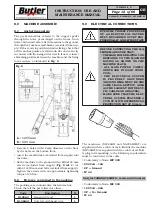
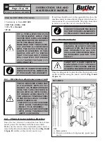
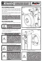
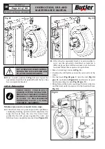
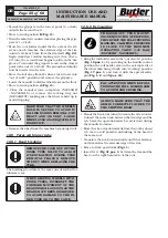
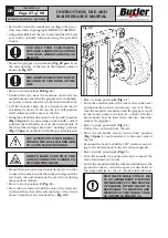
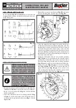
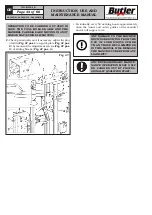
- Lock the wheel on the centring flange using the ring
nut (
Fig. 16 pos. 2
). Through the special small and
inner levers (
Fig. 16 pos. 4
) unlock the ring nut
and move it close to the star flange (
Fig. 16 pos. 1
),
therefore rotate the ring nut (
Fig. 16 pos. 2
) through
the external levers (
Fig. 16 pos. 3
) until the complete
flange clamping (
Fig. 16 pos. 1
) on the tyre;
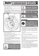
- Check both that the rim is clamped and centred
correctly, and that the wheel has been raised above
from the floor, so that it does not slip during the
operations which follow.
THE CAREFUL LUBRICATION OF THE TYRES
BEADS IS RECOMMENDED, IN ORDER TO PRO-
TECT THEM FROM POSSIBLE DAMAGES AND
TO FACILITATE MOUNTING AND DEMOUNTING
OPERATIONS.
AFTER COMPLETION OF TYRE
MOUNT/DEMOUNT OPERATIONS
DO NOT LEAVE THE WHEEL
CLAMPED ON THE SELF-CEN-
TRING CHUCK AND NEVER LEAVE
IT UNATTENDED ANYWAY.
12.6 Functioning of roll holder arm
During the working phases, the roll holder arm can
maintain two firm positions, that is:
1) “Working” position;
2) “Out of work” position.
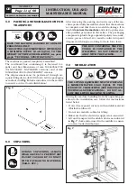
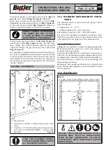
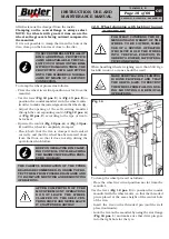
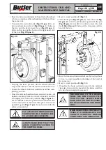
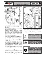
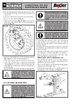
In “working” position (
Fig. 17 pos. 1
) the tool holder
arm is lowered towards the mandrel and from this
position it executes the various tyre bead breaking,
demounting and mounting operations.
Fig. 17
7503-M002-6_B
NAV26HW - NAV26HW.S - NAV26HW.ST
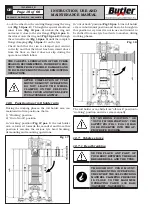
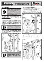
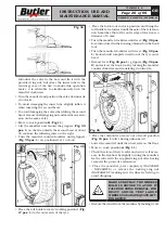
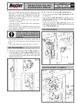
In “out of work” position (
Fig. 18 pos. 1
) the roll holder
arm is in horizontal position and has to be brought in
this position every time it is not in use and in order to
be shifted from one tyre bead side to another, during
working phases.
Fig. 18
The roll holder arm, shifts from “off-work” position to
“working” position and vice versa manually.
IN “WORKING POSITION” OR
“OUT OF WORK POSITION”, THE
SAFETY PIN (FIG. 1 POS. 12) HAS
TO BE INSERTED INTO THE AP-
PROPRIATE HOUSING.
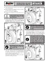
12.7 Tubeless tyres
12.7.1 Bead breaking
NEVER PLACE ANY PART OF
YOUR BODY BETWEEN THE BEAD
BREAKER ROLL AND THE TYRE.
THROUGHOUT TYRE MOUNT-
ING/DEMOUNTING OPERATIONS,
CHECK THAT THE SELF-CENTRING
MANDREL CLAMPING PRESSURE
IS CLOSE TO THE MAXIMUM
OPERATING VALUE (130 BAR)
(NAV26HW - NAV26HW.S).

