INSTRUCTION, USE AND
MAINTENANCE MANUAL
GB
Page 23 of 68
• Move to work position
B
(
Fig. 11
).
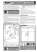
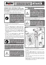
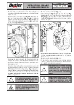
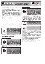
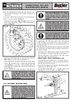
• Lower the mandrel completely. Roll the tyre on the
floor and hook it to clamp (
Fig. 28 pos. 1
)
.
• Lift the mandrel with the tyre hooked and turn it
clockwise by about 15-20 cm; the tyre will position
itself sideways with respect to the rim (see
Fig. 28
).
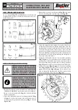
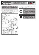
Fig. 28
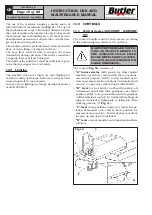
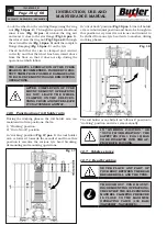
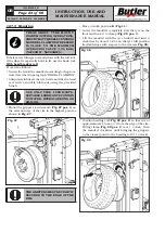
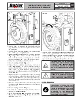
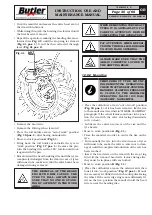
• Position beading roll (
Fig. 29 pos. 2
) so that it is at
approximately 1.5 cm (½”) from the edge of the rim.
Fitting clamp (
Fig. 29 pos. 1
) is at 1 o’clock. Turn
the mandrel clockwise until bringing the grippers
to the closest point to the beading roll (11 o'clock).
Fig. 29
7503-M002-6_B
NAV26HW - NAV26HW.S - NAV26HW.ST
12.7.3 Mounting
THROUGHOUT TYRE MOUNT-
ING/DEMOUNTING OPERATIONS,
CHECK THAT THE SELF-CENTRING
MANDREL CLAMPING PRESSURE
IS CLOSE TO THE MAXIMUM
OPERATING VALUE (130 BAR)
(NAV26HW - NAV26HW.S).
Tubeless tyre fitting is normally done with the roll tool;
if the wheel is especially hard to fit, use the hook tool.
With bead breaker roll
Proceed as follows:
• Secure the rim to the mandrel according to the proce-
dure described in paragraph “WHEEL CLAMPING”.
• Adequately lubricate the tyre beads and the rim bead
seat with a suitable lubricant using the provided
brush.
USE ONLY TYRE LUBRICANTS.
SUITABLE LUBRICANTS CONTAIN
NO WATER, HYDROCARBONS, OR
SILICON.
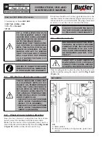
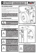
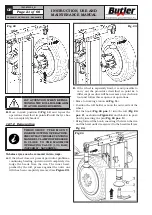
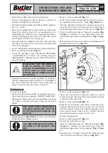
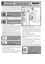
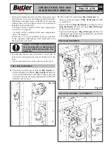
• Mount the grippers (on demand) (
Fig. 27 pos. 1
) on
the external edge of the rim in the highest point as
shown in
Fig. 27
.
Fig. 27
THE GRIPPERS MUST BE TIGHTLY
SECURED TO THE EDGE OF THE
RIM.

