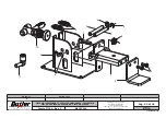
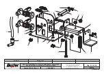
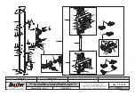
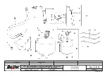
background image

Pag. 16 di 34

LISTA DEI COMPONENTI - LIST OF COMPONENTS - TEILELISTE

LISTE DES PIECES DETACHEES - LISTA DE PIEZAS

GRUPPO BASAMENTO

BASE UNIT

UNTERGESTELLSATZ

GROUPE BÂTI

GRUPO BASE

Tavola N°11 - Rev. 2 

710590920

7105-R005-11_B

SEIDO.30

SEIDO.30FI

SEIDO.30

SEIDO.30FI

Summary of Contents for SEIDO.30

Page 1: ...al dealer or call For spare parts drawings refer to the section LIST OF COMPONENTS enclosed to this manual Rev n 8 03 2018 SEIDO 30 SEIDO 30FI 7105 M005 8_B BUTLER ENGINEERING and MARKETING S p A a s u Via dell Ecologia 6 42047 Rolo RE Italy Phone 39 0522 647911 Fax 39 0522 649760 e mail Info butler it 7105 M005 8_B ...

Page 2: ...vice see Fig 14 ____________14 11 2 Pedalboard see Fig 15 _______________14 12 0 USING THE MACHINE_______________ 15 12 1 Precaution measures during tyre re moval and fitting_______________________15 12 2 Preliminary operations Preparing the wheel_______________________________15 12 3 Wheel clamping________________________15 12 3 1 Reverse wheel pan protection_______17 12 4 Bead breaking through v...

Page 3: ... pedalboard 8 Complete column 9 Filter unit pressure reducer 10 Locking device 11 Lifting device on demand KEY 1 Mandrel 2 Tool 3 Upper bead breaker 4 Lower bead breaker 5 Control panel 6 Lateral pedalboard 7 Frontal pedalboard 8 Complete column 9 Filter unit pressure reducer 10 Tubeless inflation unit 11 Locking device 12 Lifting device on demand SEIDO 30 SEIDO 30FI 7105 M005 10_B FIG 1 SEIDO 30 ...

Page 4: ...erations or jobs to be performed compulsorily Danger Be particularly careful Symbols Description Move with fork lift truck or pallet truck Lift from above Wear safety goggles Technical assistance necessary Do not perform any intervention Warning Be particularly careful possible material damages Note Indication and or useful information SEIDO 30 SEIDO 30FI 7105 M005 10_B ...

Page 5: ...te Obligation to wear protective clothing plate Tyre burst plate Inflation pedal plate Rotating parts danger plate Rotation plate Rotation direction plate Electricity danger plate Manufacturer label Serial number plate Rubbish skip label Manufacturer nameplate Controls label PLATE LOCATION ON MACHINE INFORMATION TABLE Code numbers of plates IF ONE OR MORE PLATES DISAPPEARS FROM THE MACHINE OR BECO...

Page 6: ... operation with a minimum mainte nance and care this tyre changer will operate for many years without problems thus satisfying Your needs 2 0 INTENDED USE The machines described in this manual and their different versions is a tyre changer for car tires projected to be used exclusively for the mounting demounting and inflation of wheels with dimensions of max diameter of 45 and max width of 15 THI...

Page 7: ...RULES Any tampering with or modification to the machi ne not previously authorized by the manufacturer exempts the latter from all responsibility for damage caused by or derived from said actions Removing of or tampering with the safety devices or with the warning signals placed on the machine leads to serious dangers and represents a transgression of European safety rules The machine may be used ...

Page 8: ...in the tyre keep hands away from tyre and the rim edge During inflation always stay to the side of the machine and never in front of it When operating and servicing this machine carefully follow all applicable safety and accident prevention precautions The machine must not be operated by professionally unskilled persons IN CASE OF A CHANCE SUPPLY FAILURE MOVE THE CONTROLS TO THE NEUTRAL POSITION 5...

Page 9: ...uld not be left within reach of children since it is potentially dangerous These ma terials should be deposited in the relevant collection points if they are pollutants or non biodegradable THE BOX CONTAINING THE FIXTU RES IS CONTAINED IN THE WRAP PING DO NOT THROW IT AWAY WITH THE PACKING Fig 4 7 0 MOBILIZATION THE LIFTING EQUIPMENT MUST WITHSTAND A MINIMUM RATED LOAD EQUAL TO THE WEIGHT OF THE M...

Page 10: ...o a pallet by support feet Such feet also fix the machine to the ground through anchor small blocks as shown in Fig 6 Fig 6 a 621 mm b 440 mm Fig 7 INSTALL THE MACHINE INDOORS OR IN A RO OFED AREA PLACE OF INSTALLATION MUST BE DRY ADEQUATELY LIT AND IN COMPLIAN CE WITH APPLICABLE SAFETY REGULATIONS The location of the machine requires a usable space of 3250x2750 mm as indicated in Fig 5 The positi...

Page 11: ...nstructions for bead sliding foil 1 10 2 Assembly procedures 1 Assemble Tubeless inflation unit to the machine keeping to the following instructions fix the tank Fig 8 ref 6 to the support flange Fig 8 ref 2 using the screws Fig 8 ref 4 and nuts Fig 8 ref 5 equipped on issue fix the flange Fig 8 ref 2 to the machine Fig 8 ref 3 using the screws Fig 8 ref 1 Fig 8 2 Connect the black pipe Fig 9 ref ...

Page 12: ...ions in force the machine is not equipped with a master circuit breaker but simply has a plug socket connection to the electrical mains FIT A TYPE APPROVED PLUG TO THE MACHINE CABLE THE GROUND WIRE IS YELLOW GRE EN AND MUST NEVER BE CON NECTED TO ONE OF THE PHASE LEADS MAKE SURE THAT THE ELEC TRICAL SYSTEM IS COMPATIBLE WITH THE RATED POWER AB SORPTION SPECIFIED IN THIS MANUAL AND APT TO ENSURE TH...

Page 13: ... to 43 or 45 and if necessary use a lifting device Fig 13 ref 7 5 Lock the base three screws Fig 13 ref 3 with a couple of 80 Nm 6 Place six screws Fig 13 ref 5 previously remo ved and lock them on the bases side with a couple of 80 Nm 7 Assemble again the lateral guards Fig 13 ref 1 2 of the machine NOTE after the assembly check the correct position of the tools Lock the rim on the mandrel cen tr...

Page 14: ...eaker roll When pressed in its lower part F2 it operates the downwards translation When pressed in its upper part F1 it operates the upwards translation When the push button F1 is pressed the release of the upper bead breaker roll is also operated if it has been previously introduced with push button D Push buttons G have a maintained action position and they control the vertical translation of th...

Page 15: ...ring inflation adequately lubricate the contact surface of rim and tyre bead Use specific tyre lubricants only replace the inner tube valve with a new valve If the tyre tube has a metal valve replace the grommet make sure that the tyre is the right size for the rim Never fit a tyre unless you are sure it is the right size the rated size of the rim and tyre is usually printed directly on each of th...

Page 16: ...necessary to use the proper fixture available on demand To lock a rim proceed as follows 1 Extract the central locking shaft and its cone Fig 17 ref 1 through the proper handle Fig 17 ref 2 and if necessary turn it to facilitate its extraction Fig 19 4 Insert the shaft complete with cone Fig 20 ref 1 on the rim Fig 20 ref 2 Fig 18 3 If the wheel hub is higher then the dragger Fig 19 ref 2 use the ...

Page 17: ...Fig 21 Fig 24 1 7 For wheels with alloy rims use a proper plastic guard Fig 23 ref 1 Fig 23 NEVER LEAVE THE WHEEL FIT TED ON THE MACHINE FOR A PERIOD LONGER THAN NECES SARY FOR CARRYING WORK AND IN ANY CASE NEVER LEAVE IT UNATTENDED 12 3 1 Reverse wheel pan protection In case of use of reverse wheels to protect the rim apply on the rubber platform a protection made of a transparent plastic materia...

Page 18: ...ROLLER IN ORDER TO AVOID POSSIBLE HANDS CRUSHING 3 Keep on approaching activating wheel clockwise rotation see Fig 26a pushing the pedal Fig 15 Ref A and at the same time activate the push button Fig 14 Ref F2 keeping it pressed until there s room enough for the roll to rotate for the bead breaking Then operate the roll pressing the push button Fig 14 Ref D and keep on with the bead breaking until...

Page 19: ...DS CRUSHING Fig 28 Fig 29 WHILE THIS OPERATION IS BEING CARRIED OUT PAY ATTENTION NOT TO DEFORM THE TYRE SIDE GREASE THE BEAD BEFORE THE ROLL RE ENTERS USE ONLY TYRE LUBRICANTS SUITABLE LUBRICANTS CONTAIN NO WATER HYDROCARBONS OR SILICON 7 Once bead breaking in the lower part has been completed move the lower roll to rest position activating the push button Fig 14 Ref G2 8 Rotate the rim until the...

Page 20: ...e where bead breaking has been effectuated USE VERY CAREFULLY THE TOOL HOLDER ARM IN ORDER TO AVOID POSSIBLE HANDS CRUSHING Fig 34 Fig 33 Fig 32 4 Move forward the tool so that it penetrates between rim and tyre see Fig 33 While this operation is being effectuated the tool rotates around the rim edge until it hooks the tyre bead see Fig 34 WHILE THIS OPERATION IS BEING CARRIED OUT PAY ATTENTION NO...

Page 21: ...HAT THE TOOL IS ON DEMOUNTING POSITION FIG 34 BEFORE STARTING MANDREL ROTATION 2 Therefore make the roll rotate through the provided control Fig 14 Ref E so that it is inserted betwe en the rim edge and the lower bead see Fig 40 Fig 39 1 Fig 37 8 Position the tool see Fig 38 ref 1 just next to the rim edge Using the lower bead breaking roller load the lower bead on the tool in demounting position ...

Page 22: ...2 Ref 1 onto the rim edge 3 Hook the lower bead on the tool then rotate clockwi se until the complete assembly 4 Then position the upper bead on the tool assembly area Fig 43 Ref 1 1 Fig 42 Fig 43 1 THE BEADING DISC MUST EXERT PRESSURE ON THE TYRE BEAD BUT NEVER ON THE RIM USE VERY CAREFULLY THE VER TICAL BEAD BREAKING ROLLER IN ORDER TO AVOID POSSIBLE HANDS CRUSHING WHEN THE BEADS COME OUT OF THE...

Page 23: ... assembly see Fig 46 FOR THE MOUNTING OF VERY DIFFICULT WHEELS USE THE EXTENSION OF THE BEAD DE PRESSOR FIG 46 REF 1 OP TIONAL Fig 47 8 When the operations have been completed move all the tools in rest position 12 7 Special use of the bead breaker In addition to its use during mounting and demounting the bead breaker roll can also be used for matching the tyre to the rim To conduct this operation...

Page 24: ... the tyre to inflate faster and the bead to seat easier Connect the inflation terminal to the valve of the tyre TO IMPROVE THE EFFECTIVE NESS OF TUBELESS INFLATION SYSTEM ALWAYS LUBRICATE TYRE BEADS Press the bead blaster hose on the wheel rim as shown in Fig 48 Ensure the hose head is pressed in to activate the additional air jet THE NOZZLE SHOULD BE HORI ZONTAL FOR OPTIMAL PERFOR MANCE FIG 48 Fi...

Page 25: ...e Fig 49 1 PRESSURE REGULATOR DEPRESSURE RELEASE SEMI AUTOMATIC OILER AIR SUPPLY Fig 49 IN ORDER TO ENSURE A GOOD FUNCTIONING AND TO AVOID THE PRESENCE OF CONDENSATION IN THE AIR TREATMENT UNITS WITH SEMI AUTOMATIC DRAIN IT S NECESSARY TO MAKE SURE ABOUT THE CORRECT POSITION OF THE VALVE FIG 49 REF 1 PLACED UNDER THE CAP TO ACTIVATE A CORRECT DRAIN FUNCTION THE CAP MUST BE ROTATED IN THE RIGHT WAY...

Page 26: ... 50 ANY DAMAGE TO THE MACHINE DEVICES RESULTING FROM THE USE OF LUBRICANTS OTHER THAN THOSE RECOMMENDED IN THIS MANUAL WILL RELEASE THE MANUFACTURER FROM ANY LIABILITY 13 1 Lubricants Special lubricant for mandrel movement control gear box Use ESSO GEAR OIL GX140 Lubricate slides screws nut screws or racks and pin ion with a soft brush using lubricant of ESSO GP type ANY DAMAGE TO THE MACHINE DEVI...

Page 27: ... justed Call for technical assi stance The mandrel doesn t rotate Inverter overload alarm Or Inverter undervoltage alarm Or Inverter overvoltage alarm Shorten the lenght of a possible machine extension cable or in crease the conductors section disconnect and connect again Lift the motor pedal and wait for the automatic reset Overtemperature alarm Wait until the motor system cools the machine does ...

Page 28: ...mended electric supply single phase 200 265V 50 60 Hz Maximum wheel diameter 41 43 45 Wheel max width 15 Rim locking diameter 10 26 12 28 14 30 Bead breaking power per roll 10 bar 1200 kg Vertical bead breaker max opening 900 mm Gear noise dBA 76 15 1 Weight Model without tubeless inflation 300 kg Model with tubeless inflation 318 kg SEIDO 30 SEIDO 30FI 7105 M005 10_B ...

Page 29: ...Page 29 of 38 INSTRUCTION USE AND MAINTENANCE MANUAL GB 300 467 1735 1320 715 333 875 300 467 1735 1320 715 333 875 15 2 Dimensions Fig 51 Fig 52 SEIDO 30 SEIDO 30FI 7105 M005 10_B SEIDO 30 SEIDO 30FI ...

Page 30: ...4 and subsequent amendments we communicate what follows the meaning of the crossed dustbin symbol reported on the equipment indicates that the product must not be thrown among the undifferentiated rub bish that is to say together with the mixed urban waste but it has to be managed separately to let the WEEE go through special operations for their reuse or treatment in order to remove and dispose s...

Page 31: ...T OF COMPONENTS TEILELISTE LISTE DES PIECES DETACHEES LISTA DE PIEZAS Pag 31 di 38 SCHEMA ELETTRICO ELECTRICAL SCHEME SCHALTPLAN SCHEMA ELECTRIQUE ESQUEMA ELECTRICO Tavola N A Rev 1 710505522 SEIDO 30 SEIDO 30FI 7105 M005 10_B ...

Page 32: ...omando motore Motore asincrono trifase Inverter comando motore Morsetto Micro connector Motor control potentiometer Threephase asynchronous motor Motor control inverter Clamp Verbinder Mikro Potenziometer für Motorstevevng Dreiphasen Asynchronmotor Frequenumformerantriebmotor Klemme Connecteur micro Moteur command potentiomètre Moteur asynchrone triphasé Variateur commande moteur Borne Conector co...

Page 33: ...R 5 F E R P R A B 1A 1A 2A 2A 3A 3A P R 1 1 2 3 SALITA UTENSILE TOOL RISE DISCESA UTENSILE TOOL DESCENT SALITA UTENSILE TOOL RISE DISCESA UTENSILE TOOL DESCENT 4 5 6 7 8 9 10 10 11 11 12 13 14 15 16 16 14 SALITA UTENSILE TOOL RISE DISCESA UTENSILE TOOL DESCENT 74 10 17 18 19 19 20 21 22 23 24 25 26 27 28 29 30 31 32 33 34 35 40 10 36 37 38 39 39 38 40 10 41 47 48 49 43 44 45 46 50 51 52 42 53 54 2...

Page 34: ... Rilsan Schlauch 4x2 7 röt L 2600 Rilsan Schlauch 4x2 7 röt L 240 Sperrvorrichtungszylinder Unterer Abdrücker Sperrvorrichtungszylinder Oberer Abdrücker Sperrvorrichtungszylinder Vertikalsperrvorrichtungszylinder Werkzeug Rilsan Schlauch 6x4 schwarz L 2380 Rilsan Schlauch 6x4 schwarz L 1900 Rilsan Schlauch 6x4 schwarz L 1630 Abdrücker Zylinderarme Sockel Ventil Rilsan Schlauch 8x6 schwarz L 2470 R...

Page 35: ...s 4 1 8 Rilsan Schlauch 6x4 schwarz L 2200 Rilsan Schlauch 6x4 schwarz L 1815 Pneumatischer Anschluss Y 6 Schnellablass D 6 Feststehender Verjüngungsanschluss 6 4 Rilsan Schlauch 6x4 schwarz L 2760 Verbindung V D 4 Reduktion 6 8 Optionelle Hubvorrichtung PLUS91 Optionelle 5 Wege Luftverteiler Adapterverbindung 4 8 V Verbindung 8 T Anschluss 10 10 1 8 Rilsanschlauch 10x8 schwarz L 550 Rilsanschlauc...

Page 36: ...SILE TOOL RISE DISCESA UTENSILE TOOL DESCENT 4 5 6 7 8 9 10 10 11 11 12 13 14 15 16 16 14 SALITA UTENSILE TOOL RISE DISCESA UTENSILE TOOL DESCENT 79 10 17 18 19 19 20 21 22 23 24 25 26 27 28 29 30 31 32 33 34 35 40 10 36 37 38 39 39 38 40 10 41 47 48 49 43 44 45 46 50 51 52 42 53 54 26 53 54 42 42 42 55 61 57 58 59 60 56 61 62 63 64 65 66 67 68 NERA BLACK N A N O 69 70 71 72 73 74 78 77 76 BIANCA ...

Page 37: ...rücker Sperrvorrichtungszylinder Oberer Abdrücker Sperrvorrichtungszylinder Vertikalsperrvorrichtungszylinder Werkzeug Rilsan Schlauch 6x4 schwarz L 2380 Rilsan Schlauch 6x4 schwarz L 1900 Rilsan Schlauch 6x4 schwarz L 1630 Abdrücker Zylinderarme Sockel Ventil Rilsan Schlauch 8x6 schwarz L 2470 Rilsan Schlauch 8x6 schwarz L 2570 Flussregel Rilsan Schlauch 8x6 schwarz L 1870 Zylinderarm Werkzeug Ri...

Page 38: ...nschluss 6 4 Rilsan Schlauch 6x4 schwarz L 2760 Verbindung V D 4 Reduktion 6 8 Optionelle Hubvorrichtung PLUS91 Optionelle 5 Wege Luftverteiler Adapterverbindung 4 8 V Verbindung 8 T Anschluss 10 10 1 8 Rilsanschlauch 10x8 schwarz L 550 Rilsanschlauch 10x8 schwarz L 1250 Schmierer Rilsan Schlauch 8x6 blau L 40 Ventile des Aufpumppedals Rilsan Schlauch 8x6 blau L 400 60 PSI Eichung Ventil Waage Ril...

Page 39: ...FECTUARLA EXCLU SIVAMENTE PERSONAL PROFESIONALMENTE CUALIFICADO Per eventuali chiarimenti interpellare il più vicino rivenditore oppure rivolgersi direttamente a For any further information please contact your local dealer or call Im Zweifelsfall ober bei Rückfragen wenden Sie sich bitte an den nächsten Wiederverkäufer oder direkt an Pour tout renseignement complémentaire s adresser au revendeur l...

Page 40: ...R BEAD BREAKER ARM OBERABDRÜCKARM BRAS DÉCOLLE TALONS SUPÉRIEUR BRAZO DESTALONADOR SUPERIOR Tavola N 9 Rev 1_____710590750 14 GRUPPO FRONTALE COMANDO CONTROL FRONT UNIT FRONT BEDIENUNGENSATZ GROUPE FRONTAL COMMANDE GRUPO FRONTAL MANDO Tavola N 10 Rev 2____710590740 15 GRUPPO SUPPORTO ROTAZIONE ROTATION SUPPORT UNIT ROTATIONSHALTERUNGSATZ GROUPE SUPPORT ROTATION GRUPO SOPORTE ROTACIÓN Tavola N 11 R...

Page 41: ...__710591080 28 GRUPPO STAFFA SUPERIORE GONFIAGGIO UPPER INFLATION ROD UNIT OBERES AUFPUMPBÜGELSATZ GROUPE BRIDE SUPÉRIEURE GONFLAGE GRUPO BRIDA SUPERIOR INFLADO Tavola N 23 Rev 0____710591030 29 GRUPPO BRACCIO COMANDO CONTROL ARM UNIT BEFEHLSARMSATZ GROUPE BRAS COMMANDE GRUPO BRAZO MANDO Tavola N 24 Rev 0____710590610 30 GRUPPO STAFFA CILLINDRO CYLINDER BRACKET UNIT ZYLINDERBÜGELSATZ GROUPE BRIDE ...

Page 42: ...A DEI COMPONENTI LIST OF COMPONENTS TEILELISTE LISTE DES PIECES DETACHEES LISTA DE PIEZAS Tavola N 1 Rev 5 ASSIEME GENERALE MAIN ASSEMBLY GENERALSATZ ASSEMBLAGE GENERAL JUNTO GENERAL SEIDO 30 SEIDO 30FI 7105 R005 11_B ...

Page 43: ...10591440 3 710590760 4 710590780 5 710590682 6 710590692 7 710591430 8 710591420 9 710590750 10 710590740 11 710590920 12 710591461 13 710090720 OPT OPT 14 710590130 15 710490401 16 710090920 17 710090223 18A B4127300 18B 140990371 19 710591140 20 710590570 21 710591111 22 710591080 23 710591030 24 710590610 25 710590050 26 710590370 27 710590530 OPT OPTIONAL 7105 R005 11_B SEIDO 30 SEIDO 30FI SEI...

Page 44: ...Y GENERALSATZ ASSEMBLAGE GENERAL JUNTO GENERAL 28 710090730 203129 29 710590360 30 GU4940 31 710590400 32 GU5050 33 710711010 34 710512980 35 325186 36 B1157000 37 790011620 38 710013421 39 710413660 40 272172 41 710711091 42 B1695000 43 B5815000 44 325159 45 325118 46 599442 47 599561 48 599563 49 B0622000 50 7105 R005 11_B SEIDO 30 SEIDO 30FI SEIDO 30 SEIDO 30FI ...

Page 45: ...LISTE LISTE DES PIECES DETACHEES LISTA DE PIEZAS GRUPPO COLONNA COLUMN UNIT SÄULESATZ GROUPE COLONNE GRUPO COLUMNA Tavola N 2 Rev 1 710591440 13 1 3 3 4 6 7 8 8 11 16 13 14 9 10 12 12 2 5 8 7 2 2 14 11 15 7105 R005 11_B SEIDO 30 SEIDO 30FI SEIDO 30 SEIDO 30FI ...

Page 46: ...DETACHEES LISTA DE PIEZAS GRUPPO SUPPORTO BRACCIO UNGHIA SUPERIORE UPPER TOOL ARM SUPPORT UNIT ARMTRÄGERSATZ OBEREN WERKZEUG GROUPE SUPPORT BRAS OUTIL SUPÉRIEUR GRUPO SOPORTE BRAZO UTENSILIO SUPERIOR Tavola N 3 Rev 3 710590760 7105 R005 11_B SEIDO 30 SEIDO 30FI SEIDO 30 SEIDO 30FI ...

Page 47: ...OMPONENTS TEILELISTE LISTE DES PIECES DETACHEES LISTA DE PIEZAS GRUPPO BRACCIO UNGHIA TOOL ARM UNIT ABDRÜCKARMSATZ WEKZEUG GROUPE BRAS OUTIL GRUPO BRAZO UTENSILIO Tavola N 4 Rev 5 710590780 7105 R005 11_B SEIDO 30 SEIDO 30FI SEIDO 30 SEIDO 30FI ...

Page 48: ...ISTA DE PIEZAS GRUPPO SUPPORTO BRACCIO STALLONATORE SUPERIORE UPPER BEAD BREAKER ARM SUPPORT UNIT OBERER ABDRÜCKARMTRÄGERSATZ GROUPE SUPPORT BRAS DÉCOLLE TALONS SUPÉRIEUR GRUPO SOPORTE BRAZO DESTALONADOR SUPERIOR Tavola N 5 Rev 3 710590682 7105 R005 11_B SEIDO 30 SEIDO 30FI SEIDO 30 SEIDO 30FI ...

Page 49: ...STA DE PIEZAS GRUPPO SUPPORTO BRACCIO STALLONATORE INFERIORE LOWER BEAD BREAKER ARM SUPPORT UNIT UNTERER ABDRÜCKARMTRÄGERSATZ GROUPE SUPPORT BRAS DÉCOLLE TALONS INFÉRIEUR GRUPO SOPORTE BRAZO DESTALONADOR INFERIOR Tavola N 6 Rev 3 710590692 7105 R005 11_B SEIDO 30 SEIDO 30FI SEIDO 30 SEIDO 30FI ...

Page 50: ...CIO STALLONATORE INFERIORE LOWER BEAD BREAKER ARM UNTERABDRÜCKARM BRAS DÉCOLLE TALONS INFÉRIEUR BRAZO DESTALONADOR INFERIOR Tavola N 7 Rev 2 710591430 28 1 2 3 4 31 5 6 7 8 9 9 10 11 12 13 13 12 14 15 16 15 17 18 19 20 21 22 22 23 24 24 25 26 27 29 29 30 31 7105 R005 11_B SEIDO 30 SEIDO 30FI SEIDO 30 SEIDO 30FI ...

Page 51: ...ELISTE LISTE DES PIECES DETACHEES LISTA DE PIEZAS BRACCIO STALLONATORE SUPERIORE UPPER BEAD BREAKER ARM OBERABDRÜCKARM BRAS DÉCOLLE TALONS SUPÉRIEUR BRAZO DESTALONADOR SUPERIOR Tavola N 8 Rev 4 710591420 7105 R005 11_B SEIDO 30 SEIDO 30FI SEIDO 30 SEIDO 30FI ...

Page 52: ...ENTS TEILELISTE LISTE DES PIECES DETACHEES LISTA DE PIEZAS GRUPPO FRONTALE COMANDO CONTROL FRONT UNIT FRONT BEDIENUNGENSATZ GROUPE FRONTAL COMMANDE GRUPO FRONTAL MANDO Tavola N 9 Rev 1 710590750 7105 R005 11_B SEIDO 30 SEIDO 30FI SEIDO 30 SEIDO 30FI ...

Page 53: ...E DES PIECES DETACHEES LISTA DE PIEZAS GRUPPO SUPPORTO ROTAZIONE ROTATION SUPPORT UNIT ROTATIONSHALTERUNGSATZ GROUPE SUPPORT ROTATION GRUPO SOPORTE ROTACIÓN Tavola N 10 Rev 2 710590740 1 1 2 3 4 4 5 5 5 6 6 8 9 7 10 7105 R005 11_B SEIDO 30 SEIDO 30FI SEIDO 30 SEIDO 30FI ...

Page 54: ...ONENTI LIST OF COMPONENTS TEILELISTE LISTE DES PIECES DETACHEES LISTA DE PIEZAS GRUPPO BASAMENTO BASE UNIT UNTERGESTELLSATZ GROUPE BÂTI GRUPO BASE Tavola N 11 Rev 2 710590920 7105 R005 11_B SEIDO 30 SEIDO 30FI SEIDO 30 SEIDO 30FI ...

Page 55: ...S PIECES DETACHEES LISTA DE PIEZAS GRUPPO AUTOCENTRANTE INVERTER SELFCENTERING CHUCK UNIT INVERTER AUTOZENTRIERESATZ FREQUENUMFORMER GROUPE AUTOCENTREUR VARIATEUR GRUPO AUTOCENTRANTE INVERSOR Tavola N 12 Rev 3 710591461 7105 R005 11_B SEIDO 30 SEIDO 30FI SEIDO 30 SEIDO 30FI ...

Page 56: ...TA DE PIEZAS GRUPPO STAFFA SOLLEVAMENTO A RICHIESTA LIFTING DEVICE BRACKET UNIT ON DEMAND ABZIGVORRICHTUNGBÜGELSATZ AUF ANFRAGE GROUPE BRIDE SOULÈVEMENT À DEMANDE GRUPO BRIDA LEVANTAMIENTO A DEMANDA Tavola N 13 Rev 0 710090720 1 3 2 OPT OPT 7105 R005 11_B SEIDO 30 SEIDO 30FI SEIDO 30 SEIDO 30FI ...

Page 57: ...STE LISTE DES PIECES DETACHEES LISTA DE PIEZAS GRUPPO CARTER BASAMENTO DX RH BASE GUARD UNIT UNTERGESTELLGEHÄUSESATZ R GROUPE CARTER BÂTI D GRUPO CÁRTER BASE D Tavola N 14 Rev 1 710590130 5 6 7 4 1 2 2 2 2 3 7105 R005 11_B SEIDO 30 SEIDO 30FI SEIDO 30 SEIDO 30FI ...

Page 58: ...STE LISTE DES PIECES DETACHEES LISTA DE PIEZAS PEDALIERA PER INVERTER PEDAL BOARD FOR INVERTER PEDALLEISTE FÜR INVERTER PÉDALES DE DIRECTION POUR INVERSEUR PEDALERA PARA INVERTER Tavola N 15 Rev 1 710490401 7105 R005 11_B SEIDO 30 SEIDO 30FI SEIDO 30 SEIDO 30FI ...

Page 59: ... LISTE DES PIECES DETACHEES LISTA DE PIEZAS GRUPPO TRATTAMENTO ARIA AIR TREATMENT UNIT AUFBEREITUNGLUFTSATZ GROUPE TRAITEMENT AIR GRUPO TRATAMIENTO AIRE Tavola N 16 Rev 2 710090920 1 2 3 4 5 6 7 8 2 9 10 11 12 7105 R005 11_B SEIDO 30 SEIDO 30FI SEIDO 30 SEIDO 30FI ...

Page 60: ...IST OF COMPONENTS TEILELISTE LISTE DES PIECES DETACHEES LISTA DE PIEZAS ATTACCO RAPIDO QUICK COUPLING SCHNELLANSCHLUSS BRANCHEMENT RAPID CONNEXIÓN RÁPIDA Tavola N 17 Rev 1 710090223 7105 R005 11_B SEIDO 30 SEIDO 30FI SEIDO 30 SEIDO 30FI ...

Page 61: ...STE DES PIECES DETACHEES LISTA DE PIEZAS PEDALIERA DI GONFIAGGIO INFLATION PEDALBOARD AUFPUMPPEDALERIE PÉDALES DE DIRECTION DE GONFLAGE PEDALERA DE INFLADO Tavola N 18A Rev 2 B4127300 1 2 3 4 6 5 5 6 6 7 8 9 10 11 7105 R005 11_B SEIDO 30 SEIDO 30FI SEIDO 30 SEIDO 30FI ...

Page 62: ...ZAS GRUPPO PEDALIERA GONFIATUBELESS TUBELESS INFLATION PEDALBOARD PEDALERIE TUBELESS PÉDALES DE DIRECTION DE GONFLAGE TUBELESS PEDALERA DE INFLADO TUBELESS Tavola N 18B Rev 1 140990371 1 2 3 4 5 5 6 6 6 7 8 9 10 10 11 12 13 14 4 15 15 4 9 18 18 17 16 7105 R005 11_B SEIDO 30 SEIDO 30FI SEIDO 30 SEIDO 30FI ...

Page 63: ...ATISCHERINSTALLATION GROUPE CARTER SYSTÈME PNEUMATIQUE GRUPO CÁRTER INSTALLACIÓN NEUMÁTICA Tavola N 19 Rev 1 710591140 16 1 1 2 3 4 5 6 7 8 8 8 9 9 10 10 11 11 12 12 13 14 14 15 15 16 16 16 17 17 18 19 20 21 22 22 23 24 25 25 26 27 28 29 30 30 31 32 33 34 35 36 37 38 38 39 40 41 42 43 44 44 44 45 46 47 48 49 50 51 52 53 54 16 16 16 7105 R005 11_B SEIDO 30 SEIDO 30FI SEIDO 30 SEIDO 30FI ...

Page 64: ...OF COMPONENTS TEILELISTE LISTE DES PIECES DETACHEES LISTA DE PIEZAS Tavola N 20 Rev 2 710590570 7105 R005 11_B SEIDO 30 SEIDO 30FI SEIDO 30 SEIDO 30FI GRUPPO FI EU KENDO FI EU KENDO GROUP SATZ FI EU KENDO GROUPE FI EU KENDO GRUPO FI EU KENDO ...

Page 65: ...OMPONENTI LIST OF COMPONENTS TEILELISTE LISTE DES PIECES DETACHEES LISTA DE PIEZAS GRUPPO CAVI CABLE UNIT KABELNSATZ GROUPE CÂBLES GRUPO CABLES Tavola N 21 Rev 1 710591111 7105 R005 11_B SEIDO 30 SEIDO 30FI SEIDO 30 SEIDO 30FI ...

Page 66: ...ES PIECES DETACHEES LISTA DE PIEZAS GRUPPO STAFFA SUPERIORE GONFIAGGIO UPPER INFLATION ROD UNIT OBERES AUFPUMPBÜGELSATZ GROUPE BRIDE SUPÉRIEURE GONFLAGE GRUPO BRIDA SUPERIOR INFLADO Tavola N 22 Rev 0 710591080 1 3 2 4 7105 R005 11_B SEIDO 30 SEIDO 30FI SEIDO 30 SEIDO 30FI ...

Page 67: ... COMPONENTS TEILELISTE LISTE DES PIECES DETACHEES LISTA DE PIEZAS GRUPPO BRACCIO COMANDO CONTROL ARM UNIT BEFEHLSARMSATZ GROUPE BRAS COMMANDE GRUPO BRAZO MANDO Tavola N 23 Rev 0 710591030 7105 R005 11_B SEIDO 30 SEIDO 30FI SEIDO 30 SEIDO 30FI ...

Page 68: ...ILELISTE LISTE DES PIECES DETACHEES LISTA DE PIEZAS GRUPPO STAFFA CILLINDRO CYLINDER BRACKET UNIT ZYLINDERBÜGELSATZ GROUPE BRIDE CYLINDRE GRUPO BRIDA CILINDRO Tavola N 24 Rev 0 710590610 1 6 1 3 4 5 2 2 7105 R005 11_B SEIDO 30 SEIDO 30FI SEIDO 30 SEIDO 30FI ...

Page 69: ...STA DE PIEZAS GRUPPO QUADRO VERTICALE CON ESAGONI VERTICAL PANEL UNIT WITH HEXAGONS SEITLICHESATZTAFEL MIT SECHSKANTEN GROUPE TABLEAU VERTICAL AVEC HEXAGONES GRUPO CUADRO VERTICAL CON HEXAGÓNOS Tavola N 25 Rev 0 710590050 7 1 3 2 5 4 5 6 3 7105 R005 11_B SEIDO 30 SEIDO 30FI SEIDO 30 SEIDO 30FI ...

Page 70: ...PONENTS TEILELISTE LISTE DES PIECES DETACHEES LISTA DE PIEZAS GRUPPO STAFFA MICRO MICRO BRACKET UNIT MIKROBÜGELSATZ GROUPE BRIDE MICRO GRUPO BRIDA MICRO Tavola N 26 Rev 1 710590370 3 2 5 4 1 6 7105 R005 11_B SEIDO 30 SEIDO 30FI SEIDO 30 SEIDO 30FI ...

Page 71: ...ST OF COMPONENTS TEILELISTE LISTE DES PIECES DETACHEES LISTA DE PIEZAS GRUPPO CARTER SX LH GUARD UNIT GEHÄUSESATZ L GROUPE CARTER G GRUPO CÁRTER IZ Tavola N 27 Rev 0 710590530 3 1 2 2 7105 R005 11_B SEIDO 30 SEIDO 30FI SEIDO 30 SEIDO 30FI ...

Page 72: ...COMPONENTI LIST OF COMPONENTS TEILELISTE LISTE DES PIECES DETACHEES LISTA DE PIEZAS TRASCINATORE TRACTION TOOL MITNEHMER ENTRAÎNEMENT JALADOR Tavola N 28 Rev 0 710090730 7105 R005 11_B SEIDO 30 SEIDO 30FI SEIDO 30 SEIDO 30FI ...

Reviews: