www.buyersproducts.com
Phone (440) 974-8888
Fax 800-841-8003
3
Solenoid
Assembly
Motor
Red
Red
Green
Green
Black
Black
Yellow
Red
Yellow
Socket Cover
Battery
Ground wire
5.
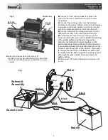
Electrical Connections (refer to Fig. 3)
A.
Before wiring, pay attention to the color of the
motor terminals and power cable. Both are color
coded.
Solenoid Assy.
Motor End
Bearing Assy.
Solenoid
Bracket
Fig. 2
Fig. 3
B.
Connect 3 short cables(coded red, black and
yellow) to the color coded terminals on the motor
accordingly.
C.
Connect the red long cable from the Solenoid
Assembly to the positive battery terminal and the black
long cable to the negtive battery terminal at one end
and to the motor ground terminal at the other end.
D.
Connect the black thin wire(ground wire) from the
Solenoid Assembly to the motor ground terminal.
E.
Lift the Socket Cover and insert the plug of the
Switch Assembly(Remote Control).
NOTE: Connecting
of the cables determines the winch operation
direction controlled by the push-buttons on the
Switch Assembly (Remote Control). After the winch
is mounted and powered, check the direction of the
Power In and Power Out on the buttons. If you wish
to change the direction on the Buttons, disconnect
the cable from the battery, switch the yellow coded
cable with the green cable. Then reconnect the
battery cables.
F.
Disconnect the Switch (Remote Control) when not
in use.


