www.buyersproducts.com
Phone (440) 974-8888
Fax 800-841-8003
4
G.
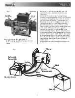
Disengage the clutch by turning the Clutch Handle
to the Disengaged position.(See Fig.4).
H.
Pull the Cable through the Fairlead and connect the
Hook and Safety Pin.
NOTE: The use of at least a 650
CCA battery is recommended.
CLOCKING INSTRUCTIONS (fig. 5)
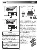
The winch gear housing can be clocked in 8 different
positions. This enables the user to locate the clutch
handle at one of 8 equally spaced points (0, 45, 90, etc.).
The winch is preset at 0.
DISENGAGED POSITION
ENGAGED POSITION
CLOCKING POSITIONS: 0° and 60°
Fig. 4
1.
Remove (2) M8x25 Tie Bar screws that attach the Gear
Housing Assembly to the Rope Drum.
2.
Separate the Gear Housing Assembly w/clutch handle
from the Tie Bars.
3.
Remove (8) M4x12 End Bearing screws.
4.
Separate the End Bearing from the Gear Ring
5.
Reposition End Bearing on the Gear Ring at desired
angle (clocked position).
6.
Replace (8) M4x12 End Bearing screws. Torque to 2
ft-lb.
7.
Align Drive Shaft, Drum Gear, and Tie Bars with Gear
Housing Assembly and reconnect.
8.
Replace (2) M8x25 Tie Bar screws. Torque to 18 ft-lb.
WINCHING OPERATION
1.
Disengage the clutch by moving the Clutch Handle to
the DISENGAGED position.
2.
Grab the Cable Assembly hook with Hand Strap and
pull the cable to the desired length, then attach to item
being pulled.
CAUTION
Always leave at least 5 turns of cable on the drum. Review
winch safety warnings and precautions on pages 1 and 2
before continuing.
3.
Re-engage the clutch by moving the Clutch Handle to
the ENGAGED position.
4.
Lift the Connector Cover on Solenoid Assy. exposing
the electrical switch connector.
WITH WIRED REMOTE CONTROL (fig. 6)
Fig. 5
Fig. 6
1.
While standing aside of the tow path, push the button
on Remote Control forward and backward (Fig. 7 and Fig.
8) to check winch running directions. Wait until the motor
stops before reversing directions.


