www.buyersproducts.com
Phone (440) 974-8888
Fax 800-841-8003
6
Programing the Receiver to a replacement
Remote(transmitter)
Hand-held Remote (transmitter) is programmed in the
factory to communicate with the receiver. Under normal
circumstances, programming will not be necessary
unless a Remote has to be replaced.
1.
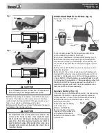
Switch on Remote (transmitter), refer to Wireless
Winching Operation step 3.
2.
Turn on the Receiver. Refer to Step 1 and 2 in Wireless
Winching Operation.
3.
Press and hold IN or OUT button on Remote till red
LED flashing.
NOTE: The programming has to be completed within
5 seconds once the Receiver is turned on. If the
programming is not completed in 5 seconds, the Receiver
will automatically reject programming. The Receiver
has to be turned off and to be restarted. Repeat the
programming procedure as described above.
LUBRICATION
1.
All moving parts within the Electric Winch have been
lubricated using high temperature lithium grease at the
factory. No internal lubrication is required.
2.
Lubricate Cable Assembly periodically using light
penetrating oil.
CABLE ASSEMBLY REPLACEMENT
1.
Move Clutch Handle to DISENGAGED position.
2.
Extend Cable Assembly to its full length.
Note how the
existing cable is connected to the inside of the drum.
3.
Remove old Cable Assembly and attach new one.
4.
Rewind Cable Assembly onto cable drum being careful
not to allow kinking.
NOTE: Performance of this winch may vary depending on
variations of vehicle and/or battery power.
WARNING
The warnings, cautions and instructions discussed in this
instruction manual cannot cover all the possible conditions
and situations that may occur. It must be understood by the
operator that common sense and caution are factors that
cannot be built into this product, but must be exercised by
the operator.
TOP LEVEL PARTS
P/N
Description
Item Number
5579500
Electric Winch, 9500 Lb
—
5571200
Electric Winch, 12000 Lb
—
ACCESSORY PARTS
P/N
Description
Item Number
5571000
Wireless Remote
—
5571001
Guide Roller
—
5571002
Shackle, 3/4"
—
5571003
Universal Mount
44
5571004
Jeep Mount
—
5571005
Receiver Mount
—
5571006
Handheld Controller, 30ft. cord —
ASSEMBLIES & KITTED SERVICE PARTS
P/N
Description
Item Number
3025773
Solenoid Assembly
31
3027944
Solenoid Mounting Bracket &
Hardware Kit
32, 33 ,34, 35 ,36, 37, 38, 39, 40,
41 ,42 ,43
3027945
Gear Ring Assembly, 9500
1, 2, 3, 4, 5, 6, 7, 8, 9, 10, 11, 12, 13,
14, 15, 16, 17, 18, 19
3027946
Gear Ring Assembly, 12000
1, 2, 3, 4, 5, 6, 7, 8, 9, 10, 11, 12, 13,
14, 15, 16, 17, 18, 19
3027947
Clutch Handle Kit
8, 9, 10, 12
3027948
Drum Assembly
23, 24, 25, 26
3027949
Cable Anchor Kit
24, 25, 26
3027950
Gasket & Seal Kit, All
7, 9, 20, 21, 22
3027951
Hardware Kit, All
2, 3, 5, 6, 10, 12, 24, 25, 26, 32, 33,
34, 35, 36, 37, 38, 39, 40, 41, 42,
43, 46, 47, 48
INDIVIDUAL SERVICE PARTS
P/N
Description
Item Number
3025772
Roller Fairlead
45
3025774
Solenoid
—
3025775
Handheld Controller, 12ft. cord 50
3025776
Galvanized Cable, 3/8" x 100' 27
3025777
Slip Hook, Clevis, 3/8"
49
3025778
Motor, Universal
30
3025779
Brake/Shaft
28
3027952
Tie Bars
29
3027953
Hand Strap
51
3027999
Decal Sheet
—
Complete Parts List


