background image


10

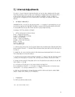
7]  Internal Adjustments 


The SOC 1.1 has a number of internal trimpots to set up the ratio calibration and the gain 
reduction metering circuit.  Full line up is a relatively complicated procedure beyond the 
scope of this manual, and should only be required if a LDR/LED module is replaced.  
Instructions for full alignment can be obtained by contacting your supplier or Buzz Audio 
directly. 


VU Meter Calibration. 

 
IMPORTANT NOTE – the LDR module inside the SOC 1.1 is sensitive to external light so do not 
perform any alignments in high light conditions.  A black cloth should be laid over the LDR 
modules (little black boxes with a dab of paint) to prevent light entering. 
 
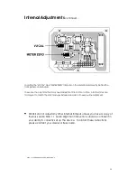
See page 10 for the location of trimpots. 


Set the front panel controls as follows: 

Drive = 0 (fully anti-clockwise) 
Output = 0dB (fully anti-clockwise) 
Attack = Auto (middle) 
Ratio = 2 (fully anti-clockwise) 
Release = Auto (fully clockwise) 
Meter = I/P (up) 
Bypass = Bypass (up) 
Link = Separate (up) 
 
1]  With the power off, remove the top panel and locate the Meter board directly behind the 
switch board of the SOC 1.1 channel. Please observe safety precautions when removing the 
top cover. 
 
2]  Adjust the V.U. meter mechanical zero (little black screwdriver adjustment on the rear of 
the meter barrel) for a mechanical zero. 
 
3]  Connect an accurate audio voltmeter to the SOC 1.1 output.  Feed into the input a 1kHz 
+4dBu (1.23V rms) signal.  The level on the external audio voltmeter should read +4dBu. 
 
4]  Apply power and switch the Bypass switch to IN, the external audio voltmeter should also 
read +4dBu (+/- 0.5 dB) 
 
5]  Locate the VU CAL trimpot on the meter board and adjust it for  
0 V.U. indication on the SOC 1.1 V.U. meter.  Change the Meter switch to O/P and check 
that the SOC 1.1 meter also indicates 0 V.U. (+/- 0.5dB). 
 
6]  Remove the input signal, change the Meter switch to G/R and locate the METER ZERO 
trimpot.  Adjust this to obtain a 0 V.U. indication. 


 Problems?


Contact your dealer or Buzz Audio. 


SOC 1.1 USERS MANUAL VERSION-4 PAGE 10


Summary of Contents for SOC 1.1 Stereo Optical Compressor

Page 1: ...Optical Compressor Users Manual SOC 1 1 USERS MANUAL VERSION 4 DEC 2009 CONTENTS COPYRIGHT BUZZ AUDIO 2001 PO BOX 6677 TE ARO WELLINGTON NEW ZEALAND VOICE FAX 64 4 385 2478 www buzzaudio com email hq...

Page 2: ...hould contact your dealer or supplier immediately for advice on what to do We also suggest you retain the original packaging at least during the warranty period in case you need to return the unit for...

Page 3: ...INTERNAL DAMAGE Selecting the Correct Fuse In the supplied accessories bag you will find 2x 1 5 Amp slow blow fuses FIT for 220V to 240V 2x 2 5 Amp slow blow fuses FIT for 110V to 120V Slide out the f...

Page 4: ...reading on the meters Other input sensitivities eg 10dBv can be supplied from the factory Note The pin 1 Signal Ground connection is intended for connecting cable SHIELDS When connecting the SOC 1 1...

Page 5: ...d Auto Attack time of the SOC 1 1 is totally dependant on the program material and the amount of gain reduction occurring This is perhaps the most musical mode when using low Ratio settings and could...

Page 6: ...itch has 3 positions I P The VU meter monitors the audio input signal as applied to the input connector G R The meter displays the amount of gain reduction or compression applied to the audio input si...

Page 7: ...move towards the right as more gain reduction occurs in the left channel than the right Important Note Unlike some other VCA based compressors all controls remain operational You MUST still set up BOT...

Page 8: ...sion are applied to vocals the fast attack position is the best choice to prevent sibilance problems When compressing a stereo mix the fast position will help control peaks in the program material get...

Page 9: ...the soft knee of the SOC 1 1 compression characteristic and is an important feature of it s design Choosing a low ratio settings for gentle control of level and thereby increasing the loudness of a so...

Page 10: ...Hz to 250kHz 3dB points with no gain reduction Harmonic Distortion less than 0 008 Measured 100Hz to 10kHz with no gain reduction Harmonic Distortion less than 0 03 Measured 100Hz to 10kHz with 20dB g...

Page 11: ...ully clockwise Meter I P up Bypass Bypass up Link Separate up 1 With the power off remove the top panel and locate the Meter board directly behind the switch board of the SOC 1 1 channel Please observ...

Page 12: ...time All other trims are factory set to match the LDR modules installed and do not need routine alignment PLEASE do not adjust any other internal trimpots unless you have a copy of the Buzz Audio SOC...

Page 13: ...replace defective parts and repair malfunctioning products under this warranty when the defect occurs under normal installation and use provided the unit is returned to our factory or duly authorised...

Page 14: ...13...

Reviews: