5
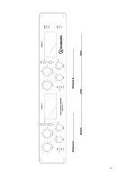
Controls and Indicators
continued…
•
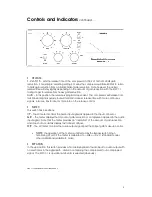
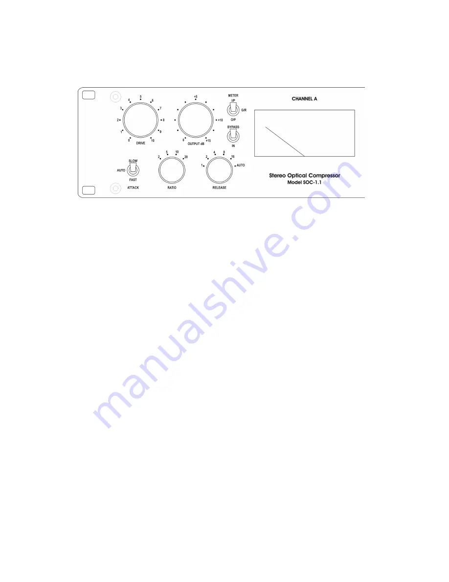
RELEASE.
1-2-4-8-16
- sets the release time of the compressor in 100’s of mS from 20dB gain
reduction. For example, selecting setting 4 means the compressor will take 400mS to return
to 0dB gain reduction from an initial 20dB of gain reduction. Note however the actual
release time will vary slightly depending on the amount of gain reduction with the SOC 1.1
taking longer to release from heavy gain reduction.
Auto
– In this position, the release is program dependent. The compressor will release from
fast transient signals quickly, but will maintain a slower release time with more continuous
signals. Also see Tips for Use for more info on the release control.
•
METER
This switch has 3 positions.
I/P
– The VU meter monitors the audio input signal as applied to the input connector.
G/R
– The meter displays the amount of gain reduction or compression applied to the audio
input signal. Note that the meter provides an “indication” of the amount of gain reduction
and does not accurately display fast transient attacks.
O/P
– The VU meter monitors the audio output signal post the Output gain make up control.
•
NOTE;
the operation of the meter is unaffected by the Bypass switch. When
monitoring I/P or O/P the meter is calibrated to +4dBu = 0 V.U. (standard model,
other calibrations available to order).
•
BYPASS/IN
In the up position, this switch provides a hard relay bypass of audio input to audio output with
no electronics in the signal path. Useful in comparing the compressed to un-compressed
signal. The SOC 1.1 is operational when IN is selected (obviously).
SOC 1.1 USERS MANUAL VERSION-4 PAGE 5
Summary of Contents for SOC 1.1 Stereo Optical Compressor
Page 14: ...13...


