background image

4

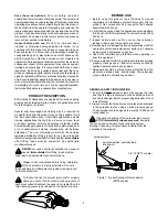
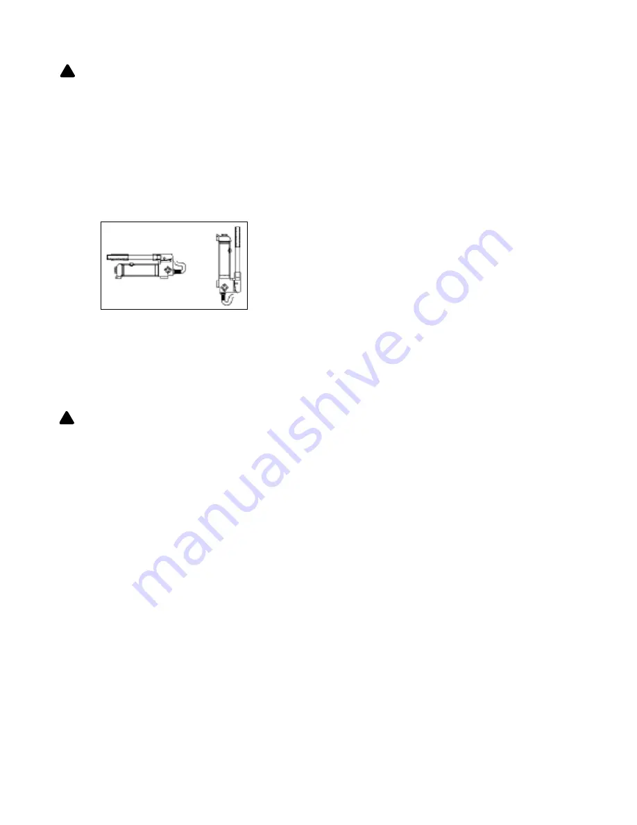
Figure 2 - Horizontal and Vertical position

OPERATION


ALWAYS monitor pressure, load or position using 

suitable equipment. Pressure may be monitored by means 

of an optional manifold and gauge. Load may be monitored 

by means of a load cell and digital indicator. 

Note:

 Any attachment that is not loaded centrally, as through 

the centerline of the ram, is considered to be “offset”. When 

extension tubes and/or offset attachments are used, the 

rated capacity is always reduced by 50% for each tube or  

offset attachment connected.

1. Pump may be used in horizontal and vertical position as 

illustrated on figure 2 below.

Changing Hydraulic Oil

For best performance and increased system life, replace the 

complete fluid supply at least once per year.

1. With ram fully lowered, remove the oil filler screw from the 

pump reservoir as above.

2. Lay the pump on its side and drain the fluid into a suitable 

container.

Note: 

Dispose  of  hydraulic  fluid  in  accordance  with  local 

regulations.

3. Set pump in its level upright position.

4. Fill with good quality jack oil to within 3/8" of the oil filler 

screw hole opening.  Reinstall oil filler screw.

Lubrication

A coating of light lubricating oil to pivot points and hinges 

will help to prevent rust and assure that pump assemblies 

move freely.

Cleaning 

Periodically check the pump piston and ram for signs of rust 

or corrosion. Clean as needed and wipe with an oily cloth.  

Note: 

Never use sandpaper or abrasive material on these 

surfaces!

Storage

When not in use, store with the pump piston and ram fully 

retracted. 

How to remove faulty coupler:

If ram does not retract,:

1. Secure load by other means.

2. Depressurize pump and hose

3. Remove the ram from application.

4. Disconnect and replace with new coupler.

Important:

 Do not attempt to grasp ram with pliers or 

wrench  without  first  wrapping  the  jaws  of  such  tool  with 

rags or similar padding.

How to bleed air from system:

1. Place pump at a higher elevation than the hose and ram 

as shown in figure 3 below.

2. Operate pump to fully extend and retract the ram 2 or 3 

times. The objective is to force the air bubbles up hill and 

back to the pump reservoir.

3. To bleed the air from pump reservoir, simply open the oil 

filler screw. Re-install after bleeding.


!

2. Locate and close release valve by turning it clockwise until 

firmly closed. (Do not over tighten)

3. Operate by pumping handle. This will send fluid from the 

pump reservoir into the high pressure hose assembly and 

into the ram assembly.

4. Continue pumping until ram reaches desired position. 


NEVER operate pump with release valve closed and 

disconnected from application. If operated in this condition, 

the hose and connections become pressurized. This 

increases burst hazard. Damage may occur to pump and 

its components.

5. To Release Pressure on work piece: Slowly, carefully turn 

the release valve counter-clockwise until ram retracts 

to desired position. Never turn release valve more than 

1/2 full turn. The ram return system is spring loaded and 

the release valve system is metered, allowing controlled 

retraction of the ram.

MAINTENANCE

1. Inspect hoses and connections daily. Replace damaged 

components immediately with BVA Hydraulics 

Replacement Parts only.

2. Tighten connections as needed. Use pipe thread sealing 

compound when servicing connections.

3. Use only good quality hydraulic fluid. We recommend BVA 

FJZ01 or equivalent. 

Never

 use brake fluid, transmission 

fluid, turbine oil, motor oil, alcohol, glycerin etc. Use of 

other than good quality hydraulic oil will void warranty and 

damage the pump, hose, and application.

Adding Hydraulic Oil

1. With ram fully lowered, set pump unit in its normal, level 

position. Locate and remove oil filler screw.

2. Fill until oil is within 3/8" of the oil filler screw hole opening, 

re-install oil filler screw.


!

Summary of Contents for SR05

Page 1: ...y MO 64153 Tel 888 332 6419 Fax 816 448 2142 E mail sales bvahydraulics com Website www bvahydraulics com SR05 M1 _012017 This is the safety alert symbol It is used to alert you to potential personal injury hazards Obey all safety messages that follow this symbol to avoid possible injury or death SR10 SR05 SR07 ...

Page 2: ...cision Immediately after lifting loads must be supported by appropriate mechanical means PRODUCT DESCRIPTION NEVER rely upon a hydraulic spreader as a support device Immediately after lifting loads must be supported by appropriate mechanical means Always check connections before using Alteration of these products is strictly prohibited Use only those adapters and attachments provided and approved ...

Page 3: ...d or reduced Periodically inspect the hose for wear Do not pull position or move ram setup by the hose Use carrying handle or other means of safe transport Do not handle pressurized hoses Never attempt to grasp a leaking pressurized hose Ensure to release the system pressure before disconnecting hydraulic hose or connections Hydraulic fluid can ignite and burn Keep hydraulic equipment away from fl...

Page 4: ...wrench without first wrapping the jaws of such tool with rags or similar padding How to bleed air from system 1 Place pump at a higher elevation than the hose and ram as shown in figure 3 below 2 Operate pump to fully extend and retract the ram 2 or 3 times The objective is to force the air bubbles up hill and back to the pump reservoir 3 To bleed the air from pump reservoir simply open the oil fi...

Page 5: ...Contact service center Ram move slower than normal Loose connection or coupler Restricted hydraulic line or fitting Pump not working correctly Ram seals leaking Tighten connection or coupler Clean and replace if damaged Check pump s operating instructions Contact service center Ram responds to pressurized fluid but system does not maintain pressure Overload condition Pump malfunctioning Ram seals ...

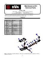
Page 6: ...DEL SR05 Maintenance Kit Service Parts SFA Companies 10939 N Pomona Ave Kansas City MO 64153 Tel 888 332 6419 Fax 816 448 2142 E mail sales bvahydraulics com Website www bvahydraulics com Item Part Number Description Qty 1 Spreader Base N A 1 2 Spreader Jaw Upper N A 1 3 C Clip 5304 00013 000 2 4 Pin F040 42004 000 1 5 Torsion Spring F040 42005 000 1 6 Piston N A 1 7 Back Up Ring 5904 00257 001 1 ...

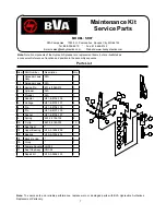
Page 7: ...448 2142 E mail sales bvahydraulics com Website www bvahydraulics com Item Part Number Description Qty 1 Spreader Jaws Assy N A 2 1 1 Spreader Jaws N A 1 1 2 Spring Pin 601 4 0060 012 1 2 Cylinder N A 1 3 Plunger N A 1 4 Adaptor H51 6 8104 109 1 5 Linkage H51 6 8105 101 4 6 Pin H51 6 8106 103 1 7 Pin H51 6 8107 105 4 8 Spacer H51 6 8108 107 4 9 Spring 522 2 0156 109 4 10 C clip 667 5 0160 003 10 1...

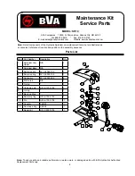
Page 8: ...Companies 10939 N Pomona Ave Kansas City MO 64153 Tel 888 332 6419 Fax 816 448 2142 E mail sales bvahydraulics com Website www bvahydraulics com Item Part Number Description Qty 1 Spreader Jaw Upper N A 1 2 Spreader Base N A 1 3 Return spring 521 2 0060 109 1 4 Return spring 521 2 0090 108 1 5 Spring pin 601 4 0030 059 2 6 Piston rod N A 1 7 O ring 1 8 Unloading pin H51 6 1202 104 1 9 O ring 1 10 ...

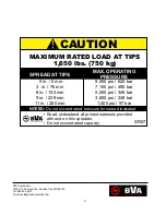
Page 9: ...E 0 in 0 mm 3 in 76 mm 6 in 152 mm 9 in 229 mm 11 in 280 mm 9 000 psi 620 bar 7 100 psi 490 bar 5 000 psi 345 bar 3 600 psi 248 bar 1 400 psi 97 bar Read understand all printed materials provided with and on this spreader Do not exceed rated capacity SFA Companies 10939 N Pomona Ave Kansas City MO 64153 Tel 888 332 6419 E mail sales bvahydraulics com ...

Page 10: ... Hydraulics product fails due to material defect in workmanship you may contact SFA for disposition In such cases the customer s sole and exclusive remedy for any breach or alleged breach of warranty is limited to the repair or replacement of the defective product Under no circumstances is BVA Hydraulics liable for any consequential or incidental damage or loss whatsoever THIS WARRANTY IS LIMITED ...

Page 11: ...SFA Companies 10939 N Pomona Ave Kansas City MO 64153 Tel 888 332 6419 E mail sales bvahydraulics com ...

Page 12: ...SFA Companies 10939 N Pomona Ave Kansas City MO 64153 Tel 888 332 6419 E mail sales bvahydraulics com ...

Reviews: