background image


INSTRUCTIONS FOR THE INSTALLATION


CWA-100/CWA-175 


1 : The supply voltage required for the unit is

 208/230 VAC with a 20 A circuit breaker. For 2 

pumps, the supply voltage required is 120 VAC 20 A. If your installation requires 3 or 4 pumps, 
provide an additional 20 A circuit breaker. 
 
2 : For a proper functioning of the machine, leave a 12’’ (30 cm.) minimum clear space around 
the condenser to facilitate air flow. 
 
3 : Install a tube of cooling line at the output of the pump. 
 
4 : Install the return of the same line at the input of the tank (to create a closed circuit). Repeat 
step 3 and 4 for each pump. 
 
Important:

 Never operate the pumps before filling the tank. 

The CWA-100 and CWA-175 are available with a minimum of two pumps. If only one pumps 
is necessary for your installation, connect the second pump in a closed circuit and always run it 
(24 hours a day) to have a constant agitation in the tank and avoid damaging the compressor.


5 : Remove the unit from the top of the tank (always use the lifting handles to raise the unit) and 
pour 7 gallons (7 X 4 liters) of glycol 100% (for an installation with 4 pumps, pour 8 gallons of 
glycol) in the tank and add water until just below the overflow. 
 
6 : Before plugging the power cord of the 

pumps, ensure that the installation and connections 

have been made to required specification. After any adjustments, plug in the pumps.  
 

7 : The level of liquid in the tank will go down until the cooling lines are filled. 
 
8 : Add water until just below the overflow and replace the unit on top of the tank. 
 
9 : Switch on the unit. Note

 there is a one minute delay before the unit start-up. For the CWA-

175, n

ote also the 3 stop/start cycles before the full start-up of the unit. 

 
10 : The temperature will slowly drop until 28⁰F (factory setting) on the thermostat display. 


Summary of Contents for BVL-056

Page 1: ...BVL Power Pack Service Specification Manual Manufactured by BVL Controls Ltd...

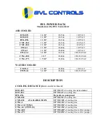
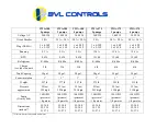
Page 2: ...HP R 404a 208 230 VAC WATER COOLED CWW 2 1 2 HP R 404a 120 VAC CWW 34 3 4 HP R 404a 208 230 VAC DESCRIPTION COOLING DISTANCE from cooler to faucet ECO 025 UP TO 25 of cooling line or ice tower ECO 03...

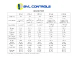
Page 3: ...83 A BTU 3120 4610 5800 5420 6700 Refrigerant R 134a R 404a R 404a R 134a R 404a Charge 18 oz 19 oz 18 oz 16 oz 21 oz Tank Capacity 12 gal 12 gal 12 gal 12 gal 12 gal Foam insulation 1 1 1 1 1 Weight...

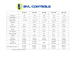
Page 4: ...13 oz 12 oz 15 oz 10 oz 10 oz Tank Capacity 3 gal 3 gal 8 gal 3 gal 8 gal Foam insulation 0 5 1 0 5 0 5 0 5 Weight 60 lb 65 lb 95lb 97 lb 92 lb Pressure approximate 18 low 150 high 18 low 150 high 18...

Page 5: ...404a R 404a R 404a Charge see label on unit 5 lb 5 lb 5 lb 6 lb 6 lb 6 lb Tank Capacity 28 gal 28 gal 28 gal 28 gal 28 gal 28 gal Foam insulation 1 1 1 1 1 1 Weight 257 lb 277 lb 297 lb 275 lb 295 lb...

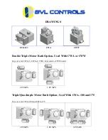
Page 6: ...Triple Motor Bath Option Used With CWA or CWW Top view for CWA 3 CWA 2 CWA 34 and also CWW units 2 PUMPS 3 PUMPS Triple Quadruple Motor Bath Option Used With CWA 100 and 175 Top view for CWA 100 and...

Page 7: ...account and will be credited upon receipt of the defective part In Canada BVL Controls Ltd 661 de la Sabliere Bois des Filion Quebec Canada J6Z 4T2 Phone 1 866 BVL CONTROLS 285 2668 Direct Line 450 9...

Page 8: ...the pump before filling the tank The pump must always run to have a constant agitation in the tank and avoid damaging the compressor 6 Replace the cover on top of the tank 7 Before plugging the power...

Page 9: ...2 gallons 2 x 4 liters for the CMV 030 and add water until just below the overflow 6 Before plugging the pump ensure that the installation and connections have been made to required specification Aft...

Page 10: ...always use the lifting handles to raise the unit and pour 3 gallons 3 X 4 liters of glycol 100 in the tank and add water until just below the overflow 6 Before plugging the pump s ensure that the ins...

Page 11: ...dles to raise the unit and pour 3 gallons 3 X 4 liters of glycol 100 in the tank and add water until just below the overflow 6 Before plugging the pump s ensure that the installation and connections h...

Page 12: ...ircuit Repeat step 3 and 4 for each pump 5 Remove the unit from the top of the tank always use the lifting handles to raise the unit and pour 3 gallons 3 X 4 liters of glycol 100 in the tank and add w...

Page 13: ...d pump in a closed circuit and always run it 24 hours a day to have a constant agitation in the tank and avoid damaging the compressor 5 Remove the unit from the top of the tank always use the lifting...

Page 14: ...every year except in very hot areas where it should be changed every six 6 months 1 Check liquid monthly a If level is low fill with water b If ice builds up remove one gallon of water and replace wit...

Page 15: ...cooler B Check applied pressure to barrel C Check equipment D Warm product lines A Adjust cooler temperature between 34 and 36 F B Adjust setting on regulator for proper pressure C Check the physical...

Page 16: ...n reservoir for liquid flow Replace pump B Replace motor C Refer to 2 D Remove from any hot water pipes or kitchen area with stove or glass washer E Remove lines from PVC thoroughly dry PVC and repair...

Reviews: