10
GB
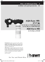
These installation and operating instructions apply
for the AQA therm HFB-1717 BA and AQA therm
HES. Both devices are available separately. This
modular system ensures optimal flexibility for every
installation situation. Using both devices ensures that
your heating system is installed and filled according
to applicable standards. Treated water has different
chemical corrosion properties. Conditioning using
inhibitors must be planned separately.
1. Safety information
I. Observe the installation instructions.
II. Use the device
- as intended
- in a perfect functioning condition
- taking safety and risk factors into consideration.
III. Please note that the device is exclusively
intended for the area of application specified in
these installation instructions. Any use above or
beyond this shall be regarded as a non-intended
use.
IV. Please note that all of the assembly, commis-
sioning, maintenance and adjustment works may
only be carried out by authorised specialists.
V. Faults that can compromise the safety of the
device must be repaired immediately.
VI. Treated water has different chemical corrosion
properties. If conditioning proves to be
necessary this should be planned separately
depending on the material
2. Functional description
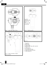
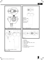
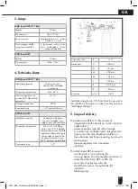
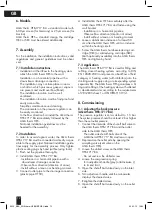
AQA therm HFB-1717 BA consists of a system se-
parator, a pressure regulator and shut-off ball valves
and is used to safely connect the heating installation
to the drinking water supply in accordance with the
applicable standards. The installed system separator
allows the heating system to be installed with the
drinking water installation. The heating system can
therefore be easily refilled at any time. The AQA
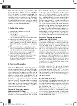
therm HES consists of a water meter, a mixing de-
vice, an optionally available softening cartridge
(AQA therm HRC) or desalination cartridge (SRC)
and a shut-off ball valve. The AQA therm HES is
used for softening/desalination.
Function of the system separator
(AQA therm HFB-1717 BA)
The system separator is a safety fitting according to
DIN EN 1717 and prevents back pressure, back-
flow and back siphonage of contaminated water
in the supply pipe, external systems or other system
parts. The system separator is divided into three
chambers (pre-chamber, intermediate chamber, and
back pressure chamber). If no water extraction takes
place, the system separator stops in an idle position
under operating pressure. The inlet and outlet side
backflow inhibitors and the drain valve are closed.
For the extraction of water, the system separator
must be in a flow position. The inlet and outlet side
backflow inhibitors are opened and the drain valve
is closed. If the differential pressure falls below 0.14
bar between the pre-pressure and intermediate pres-
sure chamber, the system separator will return to a
disconnected position (back suction). The inlet side
backflow inhibitor closes and the drain valve opens.
Function of the pressure regulator
(AQA therm HFB-1717 BA)
The pressure regulator reduces the inlet side pressure
(pre-pressure) to the desired pressure on the outlet
side (back pressure). The pressure regulator func-
tions according to the force-balance principle. The
membrane force works against the spring force of
the control valve. If following the extraction of water
the outlet pressure (back pressure) and therefore the
membrane force drops, the increased spring force
will then open the valve. The outlet pressure then
increases until a state of equilibrium returns between
the membrane and spring force. The inlet pressure
(pre-pressure) does not influence the control valve in
the pressure regulator. Pressure fluctuations on the
inlet side do not influence the back pressure (pre-
pressure compensation).
The AQA therm HFB-1717 BA can be constantly
connected to the drinking water supply via a hose
or pipe line according to DIN EN 1717 (KTW ap-
proval necessary for hose). After the completion of
the filling process, the isolating device must be acti-
vated in order to prevent an uncontrolled refilling of
the heating system.
Function AQA therm HES
The AGA therm HES installed immediately after the
AQA therm HFB-1717 BA functions according to the
principle of ion exchange and replaces the alkaline
earths found in water such as calcium and magnesi-
um with sodium ions.
Depending on the regional water hardness, the wa-
ter can either be partially or fully softened by adjus-
ting the mixing unit (or desalinated). The filling water
volume and the refill volume can be read at any time
on the installed water meter.
3329_EBA_AQA therm HFB/HES NEU.indd 10
29.02.12 10:34

