12
GB
6. Models
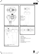
AQA therm HFB-1717 BA = standard model with
600 µm screen (for Germany) or 25 µm screen (for
Austria).
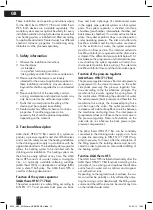
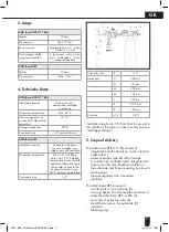
AQA therm HES = standard design, the cartridge
HRC or SRC must be ordered additionally.
7. Assembly
For the installation, the installation instructions, valid
regulations and general guidelines must be obser-
ved.
7.1 Installation instructions
- Installation at the inflow to the heating system,
attach the AQA therm HES to the wall.
- Installation in a horizontal pipeline with a
downstream drainage connection.
- The installation may not take place in rooms
or shafts in which poisonous gases or vapours
are present and could overflow (flood).
- The installation location must be well
ventilated.
- The installation location must be frost-proof and
easily accessible.
- Simplifies maintenance and cleaning.
- The manometer on the pressure regulator can
be easily monitored.
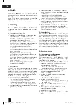
- In the flow direction first install the AQA therm
HFB-1717 BA immediately followed by the
AQA therm HES.
- National installation guidelines must be
heeded for the assembly.
7.2 Installation
In order to avoid stagnant water, the AQA therm
HFB-1717 BA must be connected as directly as pos-
sible to the supply pipe! National installation guide-
lines apply for the assembly process. Only tighten
plastic sealing plugs by hand (without using tools).
1. Flush out the pipeline thoroughly.
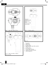
2. Install AQA therm HFB-1717 BA
- Installation in a horizontal pipeline with a
downstream drainage connection
- Observe flow direction (direction of arrow)
- Install without a tension or bending moment.
3. Connect outlet pipe to the drainage connection
(plastic pipe HT 50).
4. Install AQA therm HES immediately after the
AQA therm HFB-1717 BA and fasten using the
wall bracket
- Installation in a horizontal pipeline
- Observe flow direction (direction of arrow)
- Install without a tension or bending moment
5. Leave a stabilisation distance of at least 50
cm after the AQA therm HES until an inclusion
within the heating circuit.
6. Screw the AQA therm hardness-reducing cart-
ridge (HRC) or salt-reducing cartridge (SRC)
(both optionally available) into the AQA therm
HES and tighten by hand.
7.3 Application
The AQA therm HFB-1717 BA is used for filling and
refilling closed heating systems according to DIN
EN 12828:2003 and prevents a backflow of fluid
category 4 heating water (with inhibitors) into the
drinking water supply using a corresponding system
separator BA. The AQA therm HES guarantees a fil-
ling and refilling of the heating system with softened
or desalinated water according to the requirements
of VDI 2035 sheet 1 or ÖNORM H 5195-1.
8. Commissioning
8.1 Adjusting the back pressure
(AQA therm HFB-1717 BA)
The pressure regulator is set as default to 1.5 bar.
The system pressure should be at least 2 bar higher
than the set outlet pressure.
1. Connect the inlet side of the shut-off ball valve to
the AQA therm HFB-1717 BA and the outlet
side to the AQA therm HES
- The outlet side shut-off ball valve of the
AQA therm HFB-1717 BA must remain open
2. Depressurise the outlet side by opening the
sampling valve (vent valve on the
AQA therm HES).
3. Loosen the slotted screw on the AQA therm
HFB-1717 BA
- Do not unscrew the slotted screw
4. Loosen the compression spring
- Turn adjustment handle (grey) anticlockwise (-)
to its end limit
5. Open the shut-off ball valve slowly on the inlet
side.
6. Turn adjustment handle until the manometer
displays the desired value.
7. Retighten the slotted screw.
8. Open the shut-off ball valve slowly on the outlet
side.
3329_EBA_AQA therm HFB/HES NEU.indd 12
29.02.12 10:34

