13
GB
8.2 Flush the system
Flushing the heating system is prescribed by many
national standards. A blanking plug is therefore in-
cluded within the scope of supply of the AQA therm
HES. This can be installed instead of the AQA therm
hardness-reducing cartridge (HRC) or salt-reducing
cartridge (SRC). After flushing the system, reconnect
the cartridge for filling the system.
8.3 Adjust the softening/desalination
(AQA therm HES)
1. Measurement of the water hardness
Using the hardness measuring equipment, the
water hardness should be measured before
the installation.
Follow the information provided in the
hardness measuring equipment instructions.
2. Adjust the mixing device with the blue
adjustment handle
- The suitable dilution setting (marking 0-3 on
the casing of the mixing device, remove
insulation if necessary) is dependent on the
regional water hardness and the desired
residual hardness. The set value can be taken
from the table in the operating instructions of
the AQA therm hardness-reducing cartridge
(HRC) or salt-reducing cartridge (SRC).
8.4 Filling the system for the first time
1. Slowly open the shut-off ball valves on the inlet
and outlet sides of the AQA therm HFB-1717 BA
and on the outlet side of the AQA therm HES.
2. After filling the system, close all shut-off ball
valves. Dripping water may seep from the
discharge funnel as a result of occasional
fluctuations of pressure!
This is not a functional error and therefore
constitutes no grounds for complaint!
3. Note the filling water level, raw water hardness,
bypass setting and observe the installation and
operating instructions of the AQA therm
hardness-reducing cartridge (HRC) or
salt-reducing cartridge (SRC).
8.5 Refilling the system
Please proceed according to 8.3. Observe the ma-
ximum capacity of the AQA therm HRC or AQA
therm SRC and when reaching the capacity limit or
after one year at the most, exchange the AQA therm
hardness-reducing cartridge (HRC) or salt-reducing
cartridge (SRC).
9. Maintenance
Maintenance of system separators may only be car-
ried out by authorised personnel!
9.1 Inspection
Frequency: carried out every six months (depending
on the local conditions) by an installation company
or the BWT customer service team.
9.1.1 Functional checks of the pressure
regulators
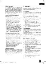
1. Connect the outlet side of the shut-off ball valve to
the AQA therm HFB-1717 BA.
2. Check the back pressure on the manometer
at zero flow
- If the pressure slowly increases, the
fitting may be contaminated or defective.
In this case, please carry out maintenance and
clean the fitting
3. Slowly open the outlet side of the shut-off ball
valve on the AQA therm HFB-1717 BA.
9.2 Maintenance
We recommend signing a maintenance contract
with an installation company or with the BWT custo-
mer service team.
In accordance with DIN EN 1717, regular mainte-
nance must be carried out.
Frequency: every one to three years (depending on
the local conditions). This should be carried out by
an installation company or the BWT customer ser-
vice team.
9.2.1 Valve insert and screen
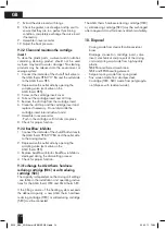
1. Connect the inlet side of the shut-off
ball valve to the AQAtherm HFB-1717 BA and
the outlet side to the AQA therm HES.
2. Depressurise by opening the sampling valve
(vent valve on the AQA therm HES).
3. Loosen the slotted screw on the AQA therm HFB-
1717 BA
- Do not unscrew the slotted screw
4. Loosen the compression spring
- Turn adjustment handle (grey) anticlockwise (-)
to its end limit
A compression spring is located in the spring
cap. A „popping out“ of the compression
spring may lead to injury.
- Please ensure that the compression spring is
slackened!
5. Unscrew the spring cap (double ended ring
spanner optionally available).
6. Remove slide ring.
3329_EBA_AQA therm HFB/HES NEU.indd 13
29.02.12 10:34

