background image

2019/08 - Indice de révision : D - Code : 29650

TRAITEMENT DE L'EAU

58/72


!

IMPORTANT

 The correlation between the Redox potential and the desired free Chlorine concentration  

should be re-established:

• 

Each year when the pool is reopened, if the pool was winterized

• 

if a significant volume of the pool water (more than 1/3) is renewed

• 

if a decision to alter the stabiliser concentration  is made

To do this you will need a photometer capable of measuring the Chlorine concentration with adequate 

precision, and that has been calibrated within the last year; if necessary adjust the concentration by 

adding small amounts of Chlorine successively, until the required concentration is reached. Note the 

Redox potential measured by EES Pro, this is the set point. If a regular drift from the Redox value is 

noticed, or if there is a sudden change in this value, replace the Redox sensor.


!

ATTENTION

 The Redox system does not allow precise regulation of the free Chlorine concentration 

at high set point values (above 2 ppm, that is approximately 725 mV at pH = 7.4).
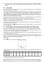
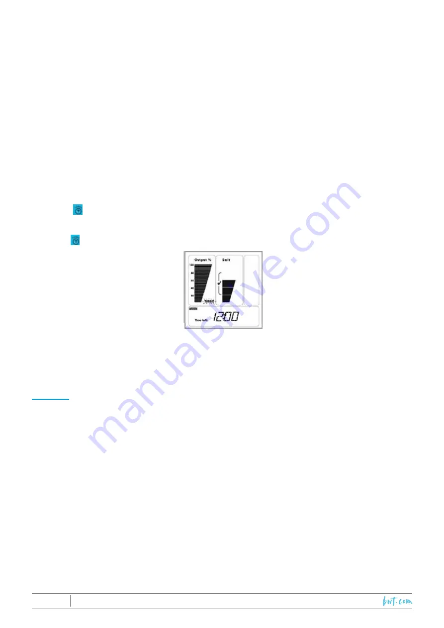
8.4 

Turbo mode

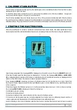
The Turbo   function allows continual production of Chlorine at maximum output (100%) over a duration 
set by the user.

Press the   button to switch to Turbo mode: the word Turbo blinks at the bottom of the output scale.

The Turbo mode duration is set to 12 hours in the factory, this setting is displayed on screen.  
Successive presses on the T button will increase the duration in increments of 12 hours up to a maximum 

duration of 72 hours (then returns to 0).

For finer adjustment, in intervals of one minute, use the arrow keys, ▲ and ▼.

EXAMPLE: 

To activate Turbo mode for a duration of 26 hours and 30 minutes. After having activated Turbo mode, 

press the T button once -> 24:00 is displayed. To set the minutes, keep the ▲ key pressed down (rapid 

scroll) and then press successively until 26:30 is displayed. If the value is overshot, use the  ▼ key to 

return to the desired value.

Next, the displayed time will start to count down, this represents the time remaining for the Turbo cycle.


!

IMPORTANT

 begin setting the duration of the Turbo cycle with the T button within 5 seconds of 

entering Turbo mode. Each successive press on the T button to modify the length of the cycle must 

occur within 5 seconds of the last. Otherwise, pressing the T button will cause the device to exit Turbo 

mode. 

There are 3 ways to exit Turbo mode:

• 

allow more than 5 seconds to elapse and then press the T button.  

• 

stop the device using the ON/OFF button

• 

set the duration of the cycle to 00 : 00

Neither activation nor exiting Turbo mode will effect settings in AUTO mode. 

Summary of Contents for EES

Page 1: ...9 08 Indice de r vision D Code 29650 TRAITEMENT DE L EAU 37 72 INSTALLATION AND OPERATING INSTRUCTIONS to be read carefully and kept for future reference EES ET ESS PRO Electrolysers FR PAGE 1 EN PAGE...

Page 2: ...tion 46 4 5 3 Procedure 47 4 5 4 When starting up for the first time 49 4 6 Installing the sensors 49 4 6 1 The REDOX sensor 49 4 6 2 pH sensor 50 4 7 Installing the electrical control panel 50 4 7 1...

Page 3: ...gh and low ph and redox alarms EES Pro only 63 9 8 1 pH HIGH 63 9 8 2 PH LOW 64 9 8 3 ORP HIGH 64 9 8 4 ORP LOW 64 9 9 Ph or redox sensor faults EES Pro only 64 9 10 pH Redox circuit board fault EES P...

Page 4: ...n which it is mounted These parameters will need to be measured regularly and the pH will need to be adjusted when necessary With the acid dosing pump option installed EES can inject acid to lower the...

Page 5: ...t When handling acid and during interventions on the pump or its tubing protective glasses and clothing should be worn to protect against splashes In the event of contact with the skin flush the area...

Page 6: ...EES Pro Electrical control panel 1 The panels of all models have the same outer appearance and the same dimensions Nevertheless the electrical spcifications functional specifications and the internal...

Page 7: ...nject acid into the hydraulic circuit The acid dosing pump kit includes 2 saddles 50 63mm 3 8 to 1 2 adaptor a check valve valve internal replacement tube 2 x 3m polyethylene tube foot filter and weig...

Page 8: ...remains in the cell In some configurations this will require installation of a check valve The flow sensor should be positioned such that the acid used to descale the cell will not touch it A check v...

Page 9: ...d air Pr cautions vis vis des sondes Les parties immerg es des sondes doivent toujours rester immerg es eau de piscine ou du robinet m me hors fonction ne doivent jamais tre touch es avec les doigts n...

Page 10: ...acid pump and saddle clamp 2 Chlorinator Cell 3 Tee with pH and ORP sensors 4 Flow switch Tee 4 5 2 Horizontal installation 1 Dosing acid pump and saddle clamp 2 Chlorinator Cell 3 Tee with pH and OR...

Page 11: ...re you wish to install the acid pump on the wall Check that the all components electrical wiring tubes etc reach their position Drill and attach the acid pump s clip to the wall and hang the pump on i...

Page 12: ...mm wrench Wrap the threads of the saddle clamp adapter to with Teflon tape and insert it into the saddle clamp Wrap the check valve threading with Teflon tape andinsert it into the adapter Cut the tub...

Page 13: ...ump in MANUAL mode for a few minutes Make sure the red light on the pump is energised that it is running and that acid is being sucked from the acid container and expelled through the injection tube 4...

Page 14: ...end of the sensor into the union until the end of the sensor is located in the centre of the pipe through which the water is flowing Screw the nut firmly onto the union and check that the sensor canno...

Page 15: ...5 m tres mais dans tous les cas plus de 2 m tres du plan d eau sous r serve que son c ble d alimentation soit directement reli un dispositif di rentiel r siduel d clenchant 30 mA exigences norme NF C...

Page 16: ...ory with acid dosing LN2 Live slaved to filtration Cover panel dry contact EES output is unchanged is no voltage is detected at the contact Flow switch Water T C sensor Cell pole Cell pole N Dosing pu...

Page 17: ...panel and acid dosing pump LD2 slaved live cell Nota bene to avoid electrical disturbances when the pump starts and stops the EES power cables should not be in contact with those of the filtration pu...

Page 18: ...buffer tank if the pool has an overflow feature and the initial salt concentration measured beforehand USE THE FOLLOWING TABLE 0 500 1000 1500 2000 2500 3000 3500 4500 10 40 35 30 25 20 15 10 5 0 20 8...

Page 19: ...e message OFF is displayed on the LCD screen Press the ON OFF button 7 If the flow of water past the flow sensor is adequate 5 m3 h the message ON EES or AUTO EES Pro indicating that production of Chl...

Page 20: ...he EES models only the chlorine output can be adjusted manually by the user by pressing the two arrow keys and This setting will be saved to memory for when the device is started in the future even if...

Page 21: ...nd maintain it at this temperature if the pool is not equipped with a heating system simply wait until the water naturally reaches the lowest temperature at which bathers will use the pool Next adjust...

Page 22: ...to switch to Turbo mode the word Turbo blinks at the bottom of the output scale The Turbo mode duration is set to 12 hours in the factory this setting is displayed on screen Successive presses on the...

Page 23: ...ion of Chlorine is decreased to 20 by default The value by which Chlorine production is decreased while the pool is covered may be modified by the user using the arrow keys and The new value will be s...

Page 24: ...n EES the cell must be removed from the hydraulic circuit for descaling 8 7 Punctual or periodic reduction of the ph by the acid dosing pump This function concerns EES Pro and also EES if the acid dos...

Page 25: ...f salt In the event of a low salt warning check that the electrodes are clean and check the salt concentration with a suitable tester in case of doubt A faulty temperature sensor could also cause a lo...

Page 26: ...along with other indicators if the salt concentration is too low as described previously 9 3 Flow rate too low The message NO FLOW and the icon appear indicating that there is either no flow or insuff...

Page 27: ...isplayed at the bottom of the LCD screen Cut power to the electrical control panel open the lid of the connection terminal compartment check the condition of the connector contacts the two wires comin...

Page 28: ...for the Chlorine concentration to fall and to see if the phenomenon reoccurs 9 8 4 ORP LOW ORP LOW this message is displayed when the value measured by the Redox sensor is less than 525 mV If no previ...

Page 29: ...agitate them Rinse the sensors thoroughly after degreasing After being descaled and degreased the sensors should be recalibrated see the next paragraph and the correspondence between the Redox potent...

Page 30: ...the filtration pump off ST BY mode close the valves of the by pass loop on which the tee housing the sensors is mounted place a bucket under the tee to collect any water Remove the pH and the Redox s...

Page 31: ...the tube until it is completely out Note It is advisable to flush the pump with running tap water in order to dilute any remaining acid which may have spilled from the tube Disconnect both ends of the...

Page 32: ...or 10 Hydrochloric acid into the cell Wait until the scale is completely dissolved stops frothing If scale is still present empty the cell and repeat the procedure with vinegar or acid Rinse the cell...

Page 33: ...erizing chemicals are added to the water to prevent the growth of algae andfiltration is run every day Filtration must notably be run while the ambient temperature in the plant room where the material...

Page 34: ...is less than 10 h day The salt concentration is barely within range Measure the salt concentration and if necessary adjust it so that it is between 4 5 and 5 0 g l Scale is starting to build up on th...

Page 35: ...l remove the lid covering the panel connection terminals and tighten the power cable connections The fuse protecting the main circuit board has blown Contact the after sales service for inspection and...

Page 36: ...2019 08 Indice de r vision D Code 29650 TRAITEMENT DE L EAU 72 72 S A au capital de 7 000 000 R C S Rennes B 333263846000 37...

Reviews: