


2019/08 - Indice de révision : D - Code : 29650
TRAITEMENT DE L'EAU
62/72
9.2
Electrical problems with the cell
2 types of electrical problems are signaled if detected:
9.2.1 Short circuit in the cell power supply circuit
The message SHRT CELL is displayed at the bottom of the screen.
•
Cut power to the control panel
•
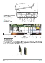
Inspect the cable linking the panel to the cell very carefully, starting at the terminal in the connection
compartment of the panel. Contact your agent if any damage is visible.
!
IMPORTANT
This message is also displayed, in parallel with other indicators if the salt concentration
is too high as described previously.
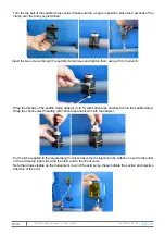
9.2.2 No current in the circuit powering the cell
(eg: the cable is cut, connector not pushed all the way in, connector contact corroded or damaged): the
message NO CELL is displayed at the bottom of the screen.
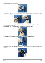
•
Cut power to the cell
•
Remove the cover over the panel connection terminals, and check that the two lugs on the cell power cable
are correctly tightened.
•
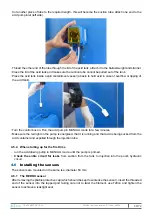
Undo the quick connectors at the cell, check that the contacts inside the connectors are not dirty (corrosion,
etc.)
•
Check that the connectors are pushed in until a 'click ' is heard.
•
Inspect the cable linking the panel and the cell carefully, starting from the terminals in the panel connection
box. Contact your agent if the cable is damaged.
!
IMPORTANT
This message is also displayed, along with other indicators, if the salt concentration is
too low as described previously.
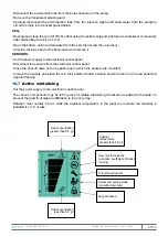
9.3
Flow rate too low
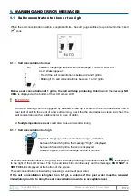
The message
NO FLOW
and the icon
appear, indicating that there is either no flow or insufficient flow
past the flow controller (subject to the reservation that the device is correctly assembled).
Stepwise resolution of the problem (if the problem is not resolved after verifying that one step is ok, move
on to the next step):
•
Check that the filtration pump motor is running;
•
Make sure that the filtration pump is primed;
•
Make sure that suction and return manifold valves in the plant room are not closed;
•
Make sure that filtration pump prefilter basket is not clogged with impurities;
•
Make sure that the filter is not clogged with impurities;
•
Make sure that the cut-off valves at the bypass loop inlet and outlet are open;
•
Close the valve between the inlet and the outlet valve on the main circuit completely so that all of the flow
is directed past the flow sensor;
•
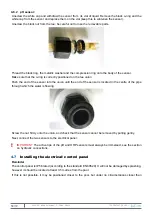
Cut power to the electrical/ control panel
, remove the lid from the panel terminal connection box,
disconnect the flow sensor cable, check the condition of the connector contacts, the two wires coming from
the cable, and the pins on the connector, then push the connector back in fully and the right way around.
•
Check the entire length of the flow sensor cable for damage.
9.4
Water temperature is too low
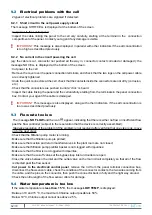
If the water temperature is
less than 15 °C
, the message
LOW TEMP
, is displayed:
•
Between 10 and 15 °C, the maximum Chlorine output possible is 50 %
•
Below 10°C, Chlorine output cannot rise above 25 %


