


UK
5
moves
hardness
from the water.
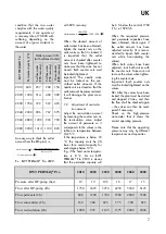
ºdH
is a term indicat-
ing the hardness of
the water and the
amount of dis-
solved salts in the
water. The lower
the number, the
softer water
3.
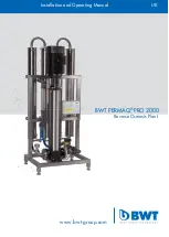
POSITIONING OF THE
PLANT
The plant must be placed in a
non-freezing environment on a
level foundation, so that the
water in the reservoir tank (op-
tion) does not overflow when the
tank is full.
The foundation must be able to
tolerate a weight load of 200 kg
in total which is the approxi-
mate weight of the RO plant in
operation. However, remember
to take into account the weight
of the softening unit and the
reservoir tank!
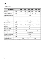
The max. outside measures of
the RO plants are WxDxH:
720 x 720 x 1690 mm, but
when positioning the plant you
must take into account that a
softening unit (option) and pos-
sibly a reservoir tank (option)
have to be installed too.
You have to allow for 1000 mm
extra height in order to be able
to take out the plant mem-
branes.
Also, there has to be made
room on the left side of the plant
for the water installation, espe-
cially the outlet hose from the
plant must be considered: The
hose may never be bent!
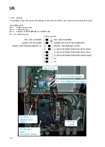
Positioning of plant must be in
such a way that the air intake at
the top of the pump never be-
comes covered.
Furthermore, there are readings
that have to be performed on
the front of the plant, e.g. flow
meter and possible alarm in
case of lacking water pressure.
Consequently the front must not
be covered up, but should al-
ways be visible.
In case of a stoppage, situations
may arise where the level in the
reservoir (option) overflows.
Therefore, there shall always be
a drain in close proximity of the
plant, placed in such a way that
the overflowing water does not
cause any damage.
If there is no floor drain which
has been dimensioned to the
full capacity of the RO unit
near the plant, installing the
plant is at your own risk.
4.
WATER QUALITY
The feed water, which is to be
treated in the BWT PERMAQ
®
Pro 2000 plant, must be sof-
tened drinking water quality
with maximum 500 mg/l TDS.
Max. temperature: 35 °C. The
plant is adjusted at 10 °C in our
factory.
The feed water may maximum
contain:
* Hardness:
0.5 °dH (obtain
Able by installation a soften-
ing unit (option))
* Fe:
0.05 mg/l
* Mn:
0.02 mg/l
* Cl:
0.1 mg/l
* Turbidity: 1.0 NTU
* SDI:
3.0 %/min
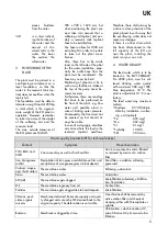
Water quality (contact BWT for technical advice)
Content
Symptom
Preventive action
TOC, BOC and
COD
Can cause slimy as well as firm hard film.
Can in some cases be micro-filtrated
or removed by means of a carbon
filter.
Iron, Manganese
(ocher)
Precipitation of iron gives a reddish-brown film and
precipitation of manganese gives a black deposit.
Sand filter – oxidation, softening,
greensand.
Calcium, magne-
sium (hard water)
The membrane scales.
Softening, antiscalant.
Silica
The membrane scales.
Antiscalant.
SDI (silt)
The membranes gets clogged.
Microfiltration (absolute), ultrafiltra-
tion, flocculation.
Oil
The membrane is greasy from oil.
Carbon filter.
Particles
The membrane gets clogged due to hard deposits.
Microfiltration.
Chlorine, pesti-
cides, organic
solvents
Membrane deformed. Permeate capacity and quali-
ty changed and cannot be CIP-cleaned back to the
original capacity. The deformation is not visible.
Free chlorine shall be removed by
active carbon filter and chemical
cleaning, either with Thiosulphate or
sulphite.
Bacteria
Membrane is clogged by slime.
Chlori de-chlorination, UV,
micro-filtration 0.2 µS/cm and ultra-
filtration.
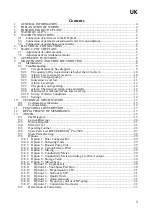
Summary of Contents for PERMAQ PRO 2000
Page 2: ...UK 2...
Page 11: ...UK 11 Alarm Transport pump 9 2 4 Indication Level low 9 2 5...
Page 19: ...UK 19 13 1 P I Diagram...
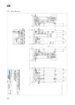
Page 20: ...UK 20 13 2 Layout Drawings...
Page 21: ...UK 21 13 3 Wiring Diagram...
Page 22: ...UK 22...
Page 23: ...UK 23...
Page 24: ...UK 24...
Page 28: ...UK 28 13 7 Spare Parts Drawing...


