26/36
2021/03 - Version: B Code : 37371
HOTLINE
WOODEN POOLS
BWT myPOOL
POOL’N BOX
8.
INSTALLATION OF THE COPING AND BOX DUCKBOARDING
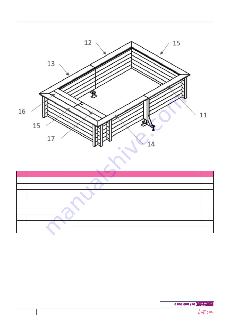
Figure 24 – Location of the coping modules
N°
DESCRIPTION
QTY
11 Coping 1684 x 195 x 28 mm, LH cut
1
12 Coping 1684 x 195 x 28 mm, RH cut
1
13 Coping 2050 x 195 x 28 mm, LH cut
1
14 Coping 2050 x 195 x 28 mm, RH cut
1
15 Coping 2370 x 195 x 28 mm
2
16 Coping 985 x 180 x 28 mm
3
17 Coping 985 x 180 x 28 mm with aperture to house the lock
1
-
Duckboarding cleat 255 x 90 x 28 mm
1
-
Duckboarding cleat 290 x 70 x 28 mm
4
8.1
Installation of the coping
Note the layout of various pool coping modules in
Figure 24
.
Orient them so that the grooved surface is facing up around the periphery of the pool. Allow a 10 mm
overhang over the inside the pool (measured from the pool wall). Take the time necessary to ensure that
the coping modules are correctly aligned and that the overlap is even. Use a cord to check that the coping
modules are aligned with each other.
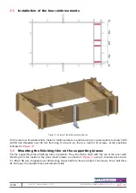
Working from underneath, screw the coping modules in position using 2 A4 SS torx hinge screws 6 × 20
(bag D) per corner coping support bracket, and 4 screws of the same type for each lefthand and righthand
coping bracket (that is a total of 56 screws).


