BXB ELECTRONICS CO., LTD.
18
Copyright © 2011 BXB ELECTRONICS CO., LTD. All rights reserved.
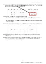
5.5 When “ID code” of speed dome has been selected press ”STEP” button move to right side to ID code
001 under ADR column
()
ID code 01 displayed under ADR column press ”UP” or ”DN” button select
the “Programmable Preset Positions” of Speed Dome.
5
◘
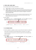
S P E E D D O M E S E T T I N G
M I C
D O M E
A D R
0 0 1
0 1
( 0 0 1 )
5.6 Each speed dome has 128 Programmable Preset Positions.
i. 4.6.7.1 When the figure under
ADR
column displayed
001
, it is the 1
st
Programmable Preset
Positions.
ii. 4.6.7.2
When the figure under
ADR
column displayed
OFF
, the function of Auto-Image Tracing &
Positioning is disabled.
5.7
When above three steps finished setting
press
”SAVE ”
button to save the setting value of the speed
dome camera
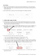
When “SAVE” button is pressed, the LCD will be displayed in the following information.
S a v e . . . . . . . . . O K
5.8 4.6.9 Now, the picture in LCD will be back to item
“b”
Repeat the above setting steps for other
conference unit.
5.9 4.6.10 The Programmable Preset Position is the 128th of ID address and the 1st ID code of the IP
speed dome. It is mainly used to turn the IP speed dome automatically to the 128th conference
preset position when there is no using microphone.


