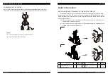

MAINTENANCE OF VEHICLES
EPS14Pi
USER MANUAL
6
8
6
9
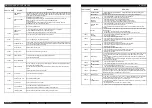
02A68
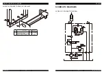
SMARTDRIVER
KO
Check whether there is a short circuit between the high-end driver of the electromagnetic brake
(CNB#1) and B-. Otherwise, the internal drive model may be damaged.
WAITING FOR
NODE
02A70
encoder error
Check the encoder of the motor.
EPS RELAY
OPEN
Check whether EPS controller is faulty.
02A71
EEPROM KO
If a fault is found in the storage area of parameters, the forklift will stop moving. If the fault
still
exists after the electric lock
is closed repeatedly, the logic card shall be replaced. If the fault
disappears, parameters stored previously will be replaced by wrong ones
and thereby being
reset.
HANDBRAKE
handbrake
02A72
VMN LOW
Causes: when starting, the high-end voltage of MOS transistor is 66% lower than that of the
capacitance or
it
is
lower than what
is required during the operation of the motor.
Possible causes:
1.
The connection or circuit of the motor is incorrect; check the three phase connection of the
motor is correct; check whether there is electric leakage in the motor connecting to the ground
or the coil of the motor disconnects.
2.
Check whether the suction of the master contactor is firm and whether the contact is worn.
3.
Replace the controller.
02A73
sens. Motor
temp.ko
Check wire harness of the temperature sensor of the motor.
02A74
DRIVER
SHORTED
Check whether a short circuit appears in the coil output by the controller. If any, replace the
controller.
AUX BATT.
SHORT.
Check whether the connection between B1 and B5 is correct. If yes, replace the controller.
DRV. SHOR. EV
Check whether a short circuit appears between the low-end of EV1/EV2/EV3 and B-. If yes,
replace the controller.
02A75
C O N T A C
T
O R
CLOSED
Before closing down the coil of the master contactor, the controller detects whether contacts
of
the master contactor adhere at first.
Try to
discharge the capacitor. If the capacitor voltage
reduces the battery voltage by 20%, a fault may occur. Recommend
to check whether contacts
of the contactor
adhere or to replace the controller.
CONTACTOR
DRIVER
When the electric lock is closed down, microcontroller will detect whether a short circuit
appears
in the driver of the master contactor. If any,
it will alarm. Check whether a short
circuit appears when the positive pole of the main contactor coil connects to A16 or the
negative pole of power supply. If the outer part is normal, replace the controller.
CONT. DRV. EV
Replace the controller.
02A76
KEY OFF
SHORTED
In the starting phase, a fault will appear when the controller detects that a low logic level
signal
is
found in disconnecting the key switch.
Fault analysis:
it
is likely that the voltage is too low. Recommend to check the following
items:
-The key switch is based on external load. (For example, DC-DC converter starts, and
the input signal of the relay or contactor is lower than starting voltage.)
-Check the connection among the power cable and positive and negative terminals of battery,
and that among the power cable and –BATT and +BATT of the master contactor and controller.
Use screws to connect with a torque range of 13NM÷15NM.
-Voltage drop will be detected on the power supply cable when the key switch is turned ON
every time.
Fault signal: The fault may occur in the hardware of the controller and thereby it is necessary to
replace the controller.
COIL SHOR. MC-
EB
1. Check whether the output and load of the controller are too high.
2. Replace the controller.
COIL SHOR. EV.
If there is a fault in a coil driven by PEV, check whether the connection between the coil driven by PEV
and the coil itself is good.
coil shorted
Check whether a short circuit appears in the coils of the master contactor and oil pump
contactor.
02A77
CONTACTOR
OPEN
1. The coil of the master contactor disconnects.
2. The master contactor is broken.
end teach ko
Not included in BYD system.
02A78
VACC NOT OK
Detecting time: the standby state
The alarm displays that the voltage of the accelerator is at least 1V higher than the
minimum value set in the accelerator signal (PROGRAM VACC).
Possible causes:
1. The upper and lower voltage limits of the accelerator are not collected. Enter the
PROGRAM VACC menu and Recollect again.
2. Error occurs in the accelerator wherein its pedal doesn’t return, or error occurs inside
the accelerator.
3. A fault occurs in the controller.
BACKING INPUT
02A79
INCORRECT
START
Possible reasons why the device starts in a wrong order are as follows:
1. Before starting up,the direction switch has been closed down.
2. The device is operated in a wrong order.
3. The wire connection is incorrect.
4. If a fault cannot be eliminated, the controller shall be replaced.
WRONG STEER
PAR.
PUMP INC START
Possible reasons why the oil pump starts in a wrong order are as follows:
1. Before starting up, switches such as those for lifting and tilting have been closed
down.
2. The device is operated in a wrong order.
3. The wire connection is incorrect.
4. If a fault cannot be eliminated, the controller shall be replaced.
02A80
FORW + BACK
The controller will always detect and alarm when requests from two directions
run signals
at the same time.
Possible causes are as follows.
1.
The wire is broken.
2.
A fault appears in the direction switch.
3.
The operation is improper.
4.
If a fault cannot be eliminated, the controller shall be replaced.
EMERGENCY
02A82
ENCODER ERROR
The controller detects that the two consecutive speed readings of the encoder are quite
different. Since the encoder inside the system is impossible to change the speed to a large
degree in a very short
time, the encoder may fail (The wiring of one or two encoders is
worn or broken). Check mechanical and circuit functions of the encoder. The alarm
may be
caused by electromagnetic
interference on the sensor bearing. If
not the above causes,
replace the controller.
Please note: Manual operation may also cause that the controller displays the fault, and
thereby the forklift needs to be powered off to restart. For example:
1.
The forklift bumps into an obstacle suddenly, making itself impossible to move.
2.
A driver slams on the brakes when the forklift is moving at high speed.
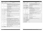
02A84
CAN BUS KO BMS
Check whether the BMS communication circuit is normal.
canbus ko bms
Check the BMS communication circuit.
02A85
VACC OUT RANGE
1. The upper and lower voltage limits of the accelerator are not collected. Enter the
PROGRAM VACC menu and Recollect again.
2. Check whether the connection of the accelerator is correct.
02A86
PEDAL WIRE KO
Check whether positive and negative terminals of the accelerator are connected to the
controller.
POS. EB.
SHORTED
When the interlock is not closed down, the high-end driver of the electromagnetic brake
outputs high voltage.
1.
Check if any other high voltage circuits are connected to the heightened outlets of
electromagnetic brakes.
2.
Otherwise, the high voltage still exists and the driving circuit inside the controller has
been broken.
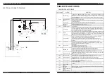
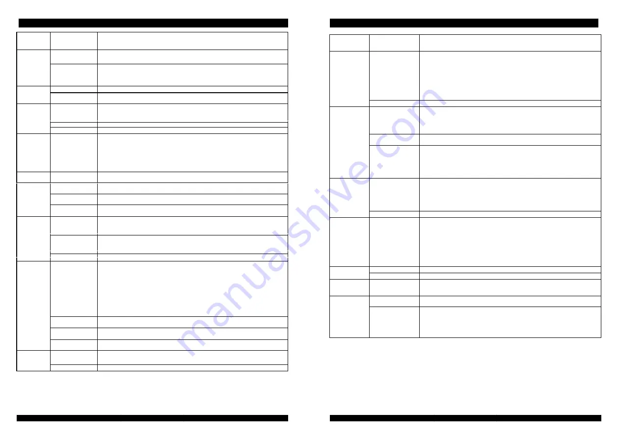
FAULT
CODE
ALARM
REMEDY
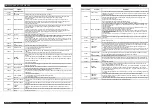
FAULT
CODE
ALARM
REMEDY
If a controller connected to another controller can’t communicate smoothly under the CAN
communication network, it will be always in a waiting state until all the CAN
communication
network works smoothly. Find out the reason why those model connections can’t communicate
smoothly, and check whether the version of the software or set of parameters is correct.
OM-
EPS14Pi
2019001-EN