background image

12

•  Risk of serious eye injury from moisture 

and debris. Operators and others in work area 

shall wear CE approved and impact-resistant eye 

protection with side shields when working with the 

compressor and/or opening the drain valve. 

•  Do not spray any part of the body.

•  Shock risk could result in death or serious injury. 

Only connect the compressor to a properly ground-

ed receptacle. 

•  Dust can be created when cutting, sanding, 

drilling or grinding materials such as wood, paint, 

metal, concrete, cement, or other masonry. To 

reduce your exposure to these chemicals, work in 

a well ventilated area and ALWAYS wear approved 

safety equipment.

• 

KEEP CHILDREN AWAY FROM THE COMPRES

-

SOR AT ALL TIMES.

CAUTION:

•  High pressure air containing water condensation 

could result in minor or moderate injury. Do not 

spray at any person.

NOTICE:

• 

If the pump has been transported or turned upside 

down (even partially), allow the pump to sit in a nor-

mal, upright position for approximately 10 minutes 

before starting.

Assembly instructions

• 

Unpack the compressor. Inspect the compressor 

for damages. If the compressor has been damaged, 

contact your dealer immediately.

• 

Check the air compressor’s identification label to ensure 

that you have purchased the intended model and that it 

has the required pressure rating for its intended use.

•  The carton should contain the compressor and 

these safety and operation instructions.

Positioning of the air compressor

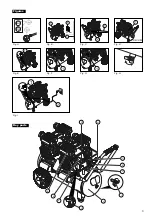
1.

 Position the air compressor (1) near an electrical 

outlet (2) (Fig. B).

2.

 The compressor must be at least 31 cm from any 

wall (3) or obstruction, in a clean, well-ventilated area 

to ensure sufficient air flow and cooling (Fig. B).

3.

 Place the compressor on the floor or a hard, level 

surface.The compressor must be level to ensure prop-

er drainage of the moisture in the tank.

Connect air hose to compressor

1.

 Connect the air hose (1) to the compressor’s quick 

coupler (2) (Fig. C).

Operating instructions

Break in the pump

1. 

Set the pressure switch (1) to the OFF position (Fig. D).

2. 

Open tank drain valve (1) by turning it counter-clock-

wise to permit the air to escape and prevent air 

pressure build-up in the air tank during the break-in 

period (Fig. E).

3.

 Turn the pressure knob (1) clockwise until it stops 

(Fig. F).

4.

 Plug in the power cord


∙ Use a dedicated circuit.


If any other electrical de

-

vices are drawing from the compressor’s circuit, 

the compressor may fail to start or an overload 

circuit can result in sluggish starting that causes 

the motor overload protection system or circuit 

breaker to trip, especially in cold conditions.


Disconnect the power cord only after break-in 

process has been completed, otherwise the 

motor might get damaged.

5. 

Set the pressure switch (1) to the ON position (Fig. 

D). The compressor will start. Run the compressor for 

30 minutes. If it fails, turn it off immediately.

Please note that breaking-in the unit is only required 

prior to first use.

6.

 After 30 minutes, turn off the pressure switch.

7.

 Close the tank drain valve (1) by turning it clockwise 

(Fig. E).

8.

 Set the pressure switch to the ON position. (Fig. D) 

The air receiver will fill to “cut-out” pressure and then 

the compressor’s motor will stop. The compressor is 

now ready for use.

Before each start-up

1. 

Set the pressure switch (1) to the OFF position (Fig. 

D).

2.

 Turn the pressure regulator knob (1) counterclock-

wise until it stops (Fig. G).

3.

 Attach hose and accessories (Fig. C)


When using an extension cord or extension cord 

reel, be sure to use a 3-core flexible cable:


◦ Up to 10m → 3 × 1.5 mm

2


◦ Up to 20m → 3 × 2.5 mm

2

.

How to start

1. 

Close the tank drain valve (1) (Fig. I)

2

. Plug-in the power cord (2) (Fig. I)

3.

 Set the pressure switch to the ON position and allow 

the tank pressure to build (Fig. D). Motor will stop 

when tank pressure reaches cut-out pressure.

4. 

Turn the air pressure regulator knob clockwise until 

desired pressure is reached (Fig. F).

5. 

The compressor is ready for use.

How to shut down

1.

 Set the pressure switch (1) to the OFF position  

(Fig. D).

2.

 Unplug the power cord (2) (Fig. I).

3.

 Set the tank drain valve (1) to ON to ensure the tank 

is drained (Fig. I).

WARNING:


Do not unplug the compressor while it is running, as 

it will cause malfunction when plugging in again, and 

pose great risk of burning the compressor unit.

!

!

Summary of Contents for 3,0HK OLIEFRI

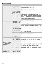
Page 1: ...ecification application and declaration of conformity Explode drawing and spare part list DA Sikkerheds og driftsvejledning Vedligeholdelse og fejlfinding V rkt jsspecifikation anvendelse og overensst...

Page 2: ...Key parts and figures 3 UK English 4 Explode drawing and spare parts 6 DA Dansk 16 Tegning og stykliste 18 2...

Page 3: ...3 Figures Fig A 2 3 1 31 cm Fig B 2 1 Fig C 1 ON OFF Fig D 1 OFF ON Fig E 1 Fig F 1 Fig G Fig H 2 1 OFF ON Fig I Key parts J I K C A B F E G H D...

Page 4: ...hat it is safe for you and others You must also make sure that the procedure work method or operating technique that you choose does not render the compressor unsafe Figures Please find the relevant f...

Page 5: ...u Alton Electrical Mechanical Industry Co Ltd N Linhu Road E Laixiu Road Foho Hi tech Development Zone Suzhou 215211 Jiangsu China declare under our sole responsibility that the BYGMA COMPRESSOR 3 0HP...

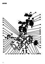
Page 6: ...6 Explode drawing...

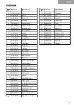
Page 7: ...03W 21 D5010003001 Crimping cap 22 J7383090034 Capacitor shroud 23 F0000901043 Heat shroud 24 J3095040201 Air filter 25 Q411A263001 Muffler tube 26 J3161200423 Elbow fitting 27 2556C273 Motor pump ass...

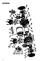
Page 8: ...8 Explode drawing motor...

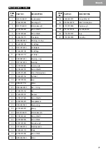
Page 9: ...16 J6993210289 Bushing 17 J0945970152 Cylinder 18 J1763720216 Bearing 19 A5562071116 Stator 20 X5530820250 Pipe O ring 21 J7026070152 Pipe 22 J7426030157 Cap 23 J0784910040 Screw M6x16 24 J6535950070...

Page 10: ...resistant eye protection with side shields Operators and others in work area shall wear hearing protection It is recommended that operator and others in work area wear CE marked helmet at the job site...

Page 11: ...g plug must be used Make sure that the product is connected to an grounded outlet that has the same configuration as the plug see Fig A No adapter should be used with this product Check with a license...

Page 12: ...n tank drain valve 1 by turning it counter clock wise to permit the air to escape and prevent air pressure build up in the air tank during the break in period Fig E 3 Turn the pressure knob 1 clockwis...

Page 13: ...ctions Monthly How to drain tank 1 Set the pressure switch 1 to the OFF position Fig D 2 Unplug the power cord 2 Fig I 3 Turn air pressure regulator knob counter clockwise to set the outlet pressure t...

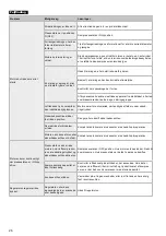
Page 14: ...et pressure switch limit The motor will start automatically when the tank pressure drops below the cut in pressure The safety valve is stuck open Clean or replace the safety valve Electrical connectio...

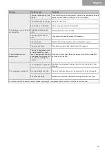
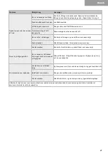
Page 15: ...to repair it The valve is leaking Check for worn parts and replace them if necessary There is moisture in the discharge air There is condensation in the air tank caused by a high level of atmospheric...

Page 16: ...og andre Du skal ogs sikre at proceduren arbejdsmetoden eller betjeningsteknikken som du v lger ikke g r kompressoren usikker Figurer De relevante figurer der refereres til i vejledningen findes p si...

Page 17: ...ou Alton Electrical Mechanical Industry Co Ltd N Linhu Road E Laixiu Road Foho Hi tech Development Zone Suzhou 215211 Jiangsu Kina erkl rer som eneansvarlige at BYGMA KOMPRESSOR 3 0HK OLIEFRI er i ove...

Page 18: ...18 Tegning...

Page 19: ...lemmed ksel 22 J7383090034 Kondensatorsk rm 23 F0000901043 Beskyttelse f cylindertop 24 J3095040201 Luftfilter 25 Q411A263001 Lydd mperr r 26 J3161200423 Kn r r 27 2556C273 Motor pumpe enhed 28 X00043...

Page 20: ...20 Tegning motor...

Page 21: ...93210289 Krans f stempelhus 17 J0945970152 Cylinder 18 J1763720216 Leje 19 A5562071116 Stator 20 X5530820250 R r O ring 21 J7026070152 R r 22 J7426030157 D ksel 23 J0784910040 Skrue M6x16 24 J65359500...

Page 22: ...m rket jenv rn med sidesk rme Brugere og andre i arbejdsomr det skal anvende h rev rn Det anbefales at brugeren og andre i arbejdsomr det anvender CE m rket hjelm p arbejdsste det Symboler p kompresso...

Page 23: ...ektriker hvis du ikke forst r jordingsanvisningerne eller du er i tvivl om hvorvidt produktet er jordet korrekt Hvis stikket ikke passer i stikkontakten skal du lade en autoriseret elektriker installe...

Page 24: ...dreje den mod uret for at lade luften slippe ud og forhindre at lufttryk opbygges i lufttanken under den f rste opstart fig E 3 Drej trykknappen 1 med uret indtil den stopper fig F 4 Tilslut kompress...

Page 25: ...aten 1 i OFF position fig D 2 Frakobl kompressoren fra stikkontakten 2 fig I 3 Drej lufttrykreguleringsknappen mod uret for at indstille udgangstrykket til nul fig G 4 Anbring en egnet beholder under...

Page 26: ...toren starter automatisk n r tanktrykket falder under udkob lingstrykket Sikkerhedsventilen sidder fast i ben position Reng r eller udskift sikkerhedsventilen De elektriske forbindelser er l se Kontak...

Page 27: ...Fors g ikke at reparere den Ventilen l kker Kontroll r for slidte dele og udskift dem om n dvendigt Der er fugt i afgangsluften Der er kondens i lufttanken for rsaget af et h jt niveau af luftfugtighe...

Page 28: ...Bygma Transformervej 12 DK 2860 S borg tlf 45 44 54 17 00 indkoeb bygma dk 12 21...

Reviews: