Section 2
– Mockup and Fit Check
BONGO bass Section 2- 4 -
½ of the threads of the adjustment screw – this is the reference point for the Bridge position.
2.
Using painters or masking tape, tape off a 3” X 4” directly behind the Bridge cavity, then position
the bridge so that the low saddle is 34” from the inside of the Nut (Figure 2.6.1).
3.
Square and center the Bridge on the pickup cavity/pickguard while ensuring that the Bridge
remains 34” from the Nut.
4.
Mark and pre-drill one of the forward Bridge holes. Attach the bridge with supplied screw (#4
on material list).
5.
Recheck Bridge position, square & center – mark and pre-drill the remaining 5 Bridge mounting
holes.
6.
Remove the Bridge.
2.6.2
Check for Bridge Ground Wire Channel
1.
Check the bridge mounting area (Figure 2.2) for the Bridge ground wire channel to the Bridge
pickup cavity.
2.
Skip to 2.7 if there is a wire channel.
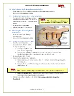
2.6.3
Drill Bridge Ground Wire Channel
1.
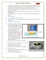
Place a piece of painters tape between
the two forward mounting holes. Mark
a spot between the forward mounting
holes, 1/4” inside and 1/8” back from
the mounting screw hole nearest the
volume controls (Figure 2.6.3).
2.
Keeping in mind that the objective is to
create a channel between the Bridge
and Bridge pickup cavity,
use extreme
caution
and drill a 3/16” hole from the
marker spot in the Bridge mounting
area to the Bridge pickup cavity, at an
angle of approximately 30 degrees, as
shown in Figure 2.6.3.
3.
Using a piece of wire, ensure that the channel is clear.
2.7
Check Rear Access Panel (#9 on material list)
1.
Check the fit of the rear access panel.
2.
Skip to 2.8 if the holes are pre-drilled.
3.
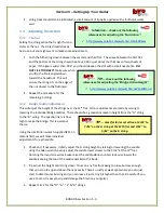
Mark and pre-drill the four access cover holes (Figure 2.7).
2.8
Check Strap Pins
1.
Check for pre-drilled holes for the Strap Pins (item 11 on the
material list), reference Figure 2.2.
2.
If the holes are pre-drilled, skip to 2.9.
Figure 2.6.3 Drill Bridge Ground wire
Figure 2.7 Access Panel Alignment
Access panel mounting screw locations:


