Section 4
– Assembly
BONGO bass Section 4
- 4 -
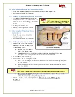
The Bridge and Neck pickups (#3 on material list) are mounted with three screws and
adjustment springs. The springs maintain pressure on the pickups so the height can be adjusted for your
playing style.
1.
Check the fit of the mounting screws on each pickup – they
should be snug but not threaded in the pickup. If the screws
do not turn freely, open the holes with a 1/8” drill using
caution not oversize the hole.
2.
Ensure that the Bridge ground wire is run through the Bridge
Pickup cavity and the channel under the Bridge to the Bridge
mounting area (Figure 2.2 and Section 2.6.3).
3.
Insert each screw into the Bridge pickup (typically with the
red
shielded signal wire). Place a spring on the screw with the
smaller side of the spring facing the pickup. Temporarily hold
the spring in place with a small piece of tape (Figure 4.4.2).
4.
Insert the Bridge Pickup signal wire through the channel into
the electrical cavity while placing the pickup into the Bridge cavity (closest to the back of the
Body). Start each adjustment screw for 2 or 3 turn. Remove the tape from each mounting
screw.
5.
Repeat steps 3 and 4 for the Neck pickup (typically with the
blue
shielded signal wire). Note the
different channel for the signal wire is in the Neck cavity.
4.4.3
Install Output Jack
Install the Output Jack (#19 on material
list) in the Body (Figure 2.2).
4.4.4
Connecting the dots
–
Soldering in the Components
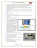
Using Figures 4.2, 4.4.1 & 4.4.4-1 as a
reference:
1.
Strip and tin the
Neck signal wire;
solder the signal wire to the Neck
Volume potentiometer pin2 and
the shield to the case of the potentiometer. (
Note
: consider dismounting the Volume control for
the soldering – access will be easier. Reinstall.).
Figure 4.4.2 Pickup Installation
Figure 4.4.4-1 Ready for Soldering
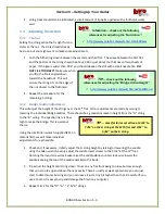
Tip
…
“tinning” a wire: stripping off approximately ¼” of insulation, then
applying solder to the exposed wire to make soldering the final connection easier


