Section 4
– Assembling Your Guitar
JEM Section 4
- 2 -
Insert the Output Jack (item #9 on the material list) through the
tunnel in the end of the Body; secure with supplied nut (align the
jack contacts to allow for easy soldering prior to tightening).
1.
Check the length of the Output jack wires – if they extend
beyond the Body, it may be easier to solder the wires to
the jack prior to inserting in the Body. Ensure that the
wires run through the nut (inside the jack pocket).
2.
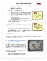
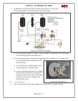
Solder the signal and ground wires to the jack (see Figure
4.2) (Note: if the signal wire is shielded, solder the shield to
the ground terminal on the jack).
3.
Install Output jack cover – pearled surface up.
4.3
Installing the Strap Pins
Secure each strap pins (2) in the pre-drilled holes with the
supplied screws (2ea, 1”).
4.4
Assemble Pick Guard, Bridge and Neck to
Body
Refer to Figure 4.4 during this section. Noted wiring colors are
typical and may vary.
4.4.1
Pick Guard & Controls Installation
1.
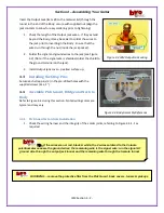
Check the wiring harness and the integrity of the solder joints, referring to Figure 4.4.1-1 as
required.
reminder
…
remove the protective film from the Pick Guard, back covers, tuners & pickups
Figure 4.4 Body Assembly Reference
Tip
…
if the wires are not red, black & white, the 2 wires soldered to the Volume
potentiometer case are the ground wires; the remaining wire is the signal wire: run the signal & 1
ground wire through the output jack tunnel and the remaining wire through the tremolo tunnel
Figure 4.2 JEM Output Jack wiring


