Section 2
– Mockup & Fit Check
SG Section 2- 4 -
2.5
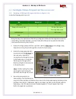
Check for Bridge Ground Tunnel
In order to minimize audio hum and pickup, the
electrical components are grounded together. This
check ensures that there is a tunnel for routing the
Bridge ground wire to the Bridge mounts. Reference
Figure 2.0 for the layout of electrical component and
wiring
–
specifically the Bridge Ground wire tunnel, as
shown in Figure 2.5 where a tunnel connects the Bridge
pickup cavity to the Bridge mounting hole. Proceed to
Paragraph 2.6 if there is a tunnel.
2.5.1
Drilling the Bridge Ground Tunnel
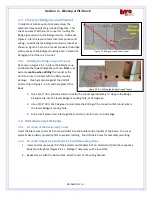
As shown in Figure 2.5.1-1, place the Body face up
and locate the lower Bridge Mount hole.
Note:
use
extreme
caution when drilling
the tunnel as the
drill can come in contact with the Body causing
damage. Placing material against the drill bit
(white strip in Figure 2.5.1-1) will help protect the
Body.
1.
Use a 3/32” drill, pre
-
dill a starter hole for the tunnel approximately ¼” deep in the
Bridge
Pickup cavity into the lower Bridge mounting hole, at 45 degrees;
2.
Use a 5/32” drill, at 45 degrees, to complete the drilling of the tunnel so that tunnel enters
the lower Bridge mounting hole;
3.
Run a small piece of wire through the tunnel to ensure there is no blockage.
2.6
Miscellaneous Fit Checks
2.6.1
Fit check of the back-cavity Cover
Insert the black cover (item #10 on material list) into the Audio control pocket of the body
–
the cover
typically has a plastic protective film to avoid scratching. Pre-drill the 4 holes for assembly mounting.
2.6.2
Fit check Output Jack and Selector Switch Mounting Holes
1.
Insert and ensure proper fit of the Selector switch (item #15 on material list) into the respective
Body mounting hole (Figure 2.2.1). Enlarge if necessary with a round file;
2.
Repeat step 1 with the Output Jack, which is part of the wiring harness.
Figure 2.5 Bridge Ground Wire Tunnel
Figure 2.5.1-1 Drilling the Bridge Ground Tunnel


