Section 4
– Assembly
SG Section 4- 5 -
1.
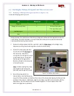
Lay the wiring harness over the Body back
with the Volume & Tone controls and the
Audio jack over the Audio pocket;
2.
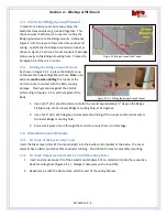
Using caution for the Body finish and the
supplied flat washers and nuts, mount (do
not tighten yet) the Neck & Bridge Volume
controls, (with the Bridge ground wire
soldered to the case, typically white), as
shown in Figure 4.2.1-2;
3.
Run the Bridge ground wire from the Neck
Volume control through the tunnel to the
Bridge Pickup pocket;
4.
Mount the Bridge Volume & Tone controls;
5.
Mount the Output Jack;
4.2.2
Install Pickups
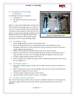
The pickups are installed as shown in Figure 4.2.2
where the Neck pickup has a smaller taper than the
Bridge pickup. Also note that the pickups are
mounted with the small dimension of the taper
pointed toward the neck.
1.
Run the shielded pickup wire from the Neck
pocket to the Audio pocket via the tunnel
–
mark the end with tape;
2.
Mount the Neck pickup with 2 screws
–
do
not tighten, also note the orientation of the
connection pins;
3.
Run the shielded pickup wire from the Bridge pocket to the Audio pocket via the tunnel;
4.
Mount the Bridge pickup with 2 screws
–
do not tighten.
4.2.3
Install Volume Control Wiring
1.
Solder the Neck pickup signal wire
(marked with tape, typically white) to pin 2 on the Neck Tone control
–
consider removing the
tone control, soldering, then replacing as it might be easier to solder;
Figure 4.2.1-1 SG Body Wiring Reference
Figure 4.2.1-2 Installed Audio components
Figure 4.2.2 Pickup Installation
Tip
…
Consider removing each Tone control to
solder the wiring
–
then re-install

