2
Operation and Maintenance Instructions for CAT-Xpress Spray Guns
Operation
1. Connect air supply hose at handle of gun.
2. Connect a pressurized fluid supply to the gun fluid inlet.
3. Fluid flow can be controlled using the fluid control knob, this restricts flow by limiting needle travel. It is best to control
fluid flow by proper selection of fluid orifice size and use the fluid control knob to “fine tune flow rate”.
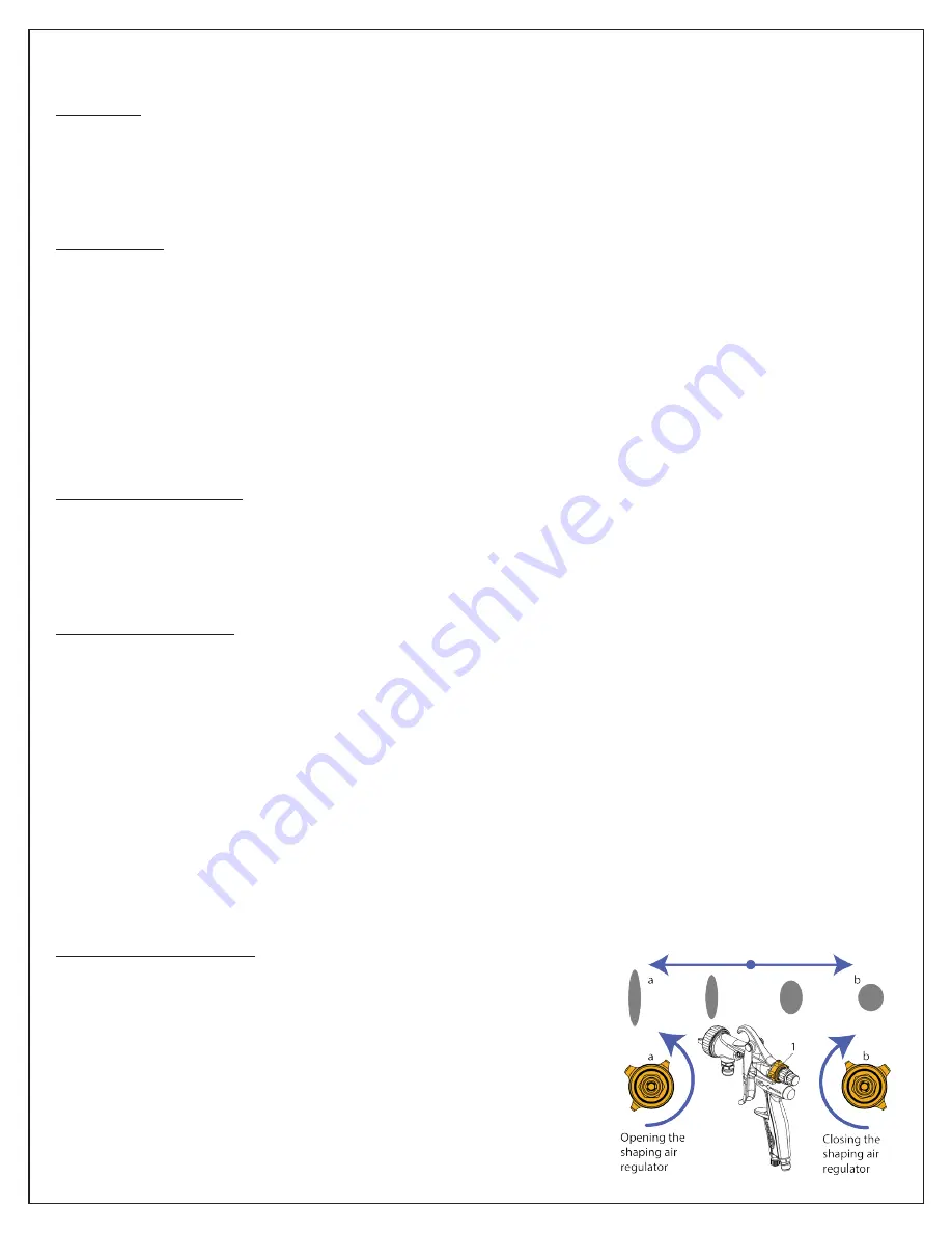
4. Fan width can be adjusted using the fan control knob. Turning the knob clockwise narrows the fan.
Maintenance
IMPORTANT! Routine cleaning and maintenance is essential to insure proper gun operation. Several states prohibit spraying
solvent into the atmosphere and require the use of covered gun cleaner.
1. If a gun cleaner is being used, connect and clean the gun in the gun cleaner according to the manufactures instructions.
2. If a gun cleaner is not being used:
Remove air cap and clean separately using clean solvent. For pressure setups, connect a pressurized solvent supply to the
fluid inlet, trigger the gun allowing solvent to flow thru the gun until clean.
NOTE: Gun head disassembly is not recommended for normal cleaning and maintenance.
Gun head disassembly and reassembly instructions:
Have repair kit # 2411779
available before gun disassembly.
Gun head disassembly
To remove the nozzle carrier (8):
1. Remove the air cap (1 & 4), fluid nozzle body (5), baffle (6), fluid nozzle (7), and needle (26).
2. Remove the needle seal cartridge (10).
3. Loosen the locknut (12) and remove fluid inlet (13) using a 5/8” open-end wrench.
4. The nozzle carrier (8) and o-ring (9) will now slide forward from the gun body (40).
Gun head reassembly
1. Install a new o-ring (9) on the fluid nozzle body carrier (8).
2. Install the thread locknut (12) onto the fluid inlet (13) as far as possible.
3. Install a new fluid inlet seal (11) into the recess area on the fluid nozzle body carrier (8) inlet port.
4. Slide the fluid nozzle body carrier (8) into the gun body (40) as far as possible. Be sure the fluid nozzle body carrier (8)
extends into the hole at the back of the gun head. Install the needle seal (10) but do not tighten.
5. Rotate the fluid nozzle body carrier (8) until the fluid inlet port in the nozzle body carrier (8) is aligned with the threaded
hole in the gun body (40). While in this position, insert the fluid inlet (13) and tighten firmly. Locknut (12) should already
be threaded onto the fluid inlet (13).
6. Tighten the needle seal (10) to approx. 12 ft.-lb. torque.
7. Tighten the fluid inlet (13) to approx. 25 ft.-lb. torque.
8. Tighten the locknut (12) to approx. 33 ft.-lb. torque.
9. Install baffle (6) into gun body (40) with the holes facing inward towards the gun body. Make sure to line up to pins.
10. Install fluid nozzle (7) into nozzle body (5), then thread and tighten into fluid nozzle body carrier (8).
11. Install air cap (4) into the air cap ring (1). Sealing ring (2) and o-ring (3) should already be installed in the air cap ring (1).
then thread onto the gun body’s (40) head assembly.
Fan control disassembly
To remove the fan control (29):
1. Remove the rear fluid adjustment knob assembly (36 - 39) along with the
fluid needle (28).
2. Make sure the fan adjustment knob (32) is in the open position (turned
counter clockwise when pointed away from you).
3. Please note step 4 and back out the fan control sleeve (35) counter clockwise.
4. As you back out the fan control sleeve (35), the housing (31) will want to
move inward into the body. When this happens, alternate between turning
the adjustment knob (32) counter clockwise and backing out the contol
sleeve (35). Repeat until the fan control assembly fully backs out.